Classic iSensor physical deployment guide
Classic Taegis NDR iSensor is being replaced by Sophos NDR.
For migration options, see Migrate to Sophos NDR.
The classic iSensor is installed on your network where it monitors all network traffic, leverages our latest threat intelligence to detect network-level threats, and sends detections to Sophos XDR when malicious traffic is detected.
The following features are supported:
- Inline and passive deep packet inspection
- Integration of Sophos Counter Threat Unit™ (CTU) threat intelligence
- Ability to block malicious traffic on the network
Data provided by this integration
Data provided by the classic iSensor gets normalized to the following schemas:
netflownids
For more information about using schemas in Data Lake Search, see Schemas.
Requirements
Review the following requirements prior to implementation.
Connectivity requirements
| Source | Destination | Protocol and port |
|---|---|---|
| Classic iSensor (mgmt IP) | 206.55.100.0/22 216.9.204.0/22 208.89.40.0/21 | TCP/443 (unproxied) |
TCP/443 traffic must be excluded from any web content filtering devices. Without an exclusion, the TCP/443 traffic will be inspected and dropped by most web content filtering devices as malformed HTTPS traffic.
Maximum transmission unit (MTU)
There are two classic iSensors based on software image with differing supported MTU sizes:
- Standard: Packets that will traverse the Standard IPQ3 or 3G/10G IPQ3 classic iSensor should have a MTU of 1522 or less. Anything higher will lead to packet loss and have a negative impact on network connectivity.
- High Speed: The High Speed classic iSensor running DPDK is able to support an MTU of up to 9000. If you wish to use the non-default MTU size of 1500, inform your implementation engineer during implementation discussions.
Note
The MTU size is applied to all of the classic iSensor's monitoring interfaces. This means that if the classic iSensor is monitoring multiple network segments, all segments must have the same MTU.
Physical requirements
- The default static rail shipped with the Dell Server is compatible with both two-post and four-post racks. If desired, there is an optional sliding rail available that is only compatible with four-post racks.
- A monitor and USB keyboard connected to the classic iSensor.
- Connection from the management interface of the classic iSensor to the network. See Interface diagrams.
- Connection of the included power cable(s) to the classic iSensor.
- Device powered on.
Contact your account representative to walk you through the rest of the implementation.
Physical setup
Interface diagrams
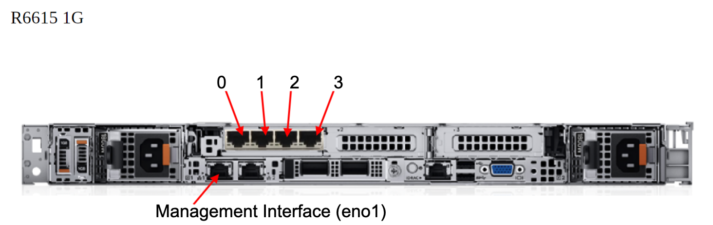
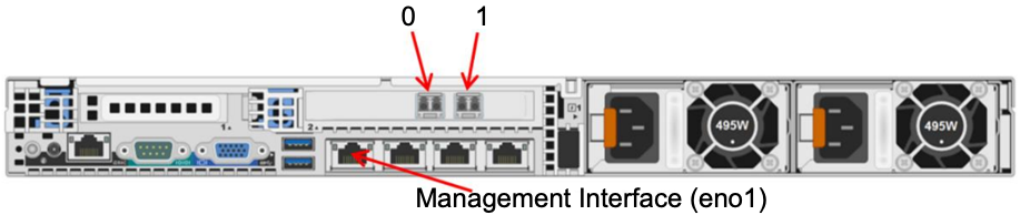
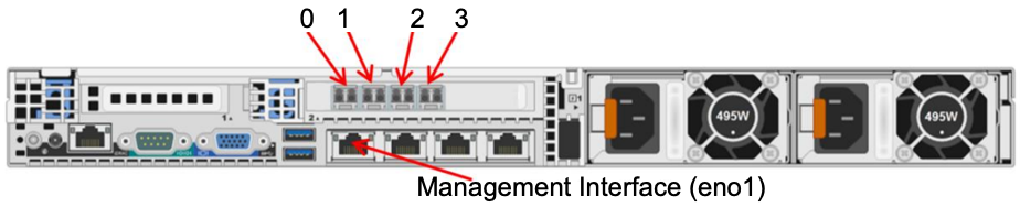
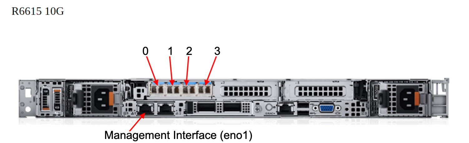
The following images show the interface diagrams of supported classic iSensor hardware models:
-
Standard four-port classic iSensor (PER320):

-
Standard four-port classic iSensor (PER330):
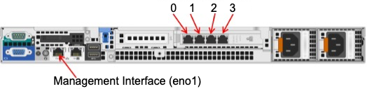
-
Standard four-port classic iSensor (R340XL):
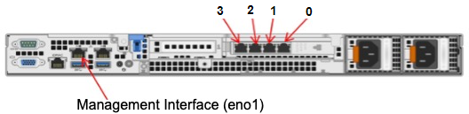
-
Standard four-port classic iSensor (PER360):
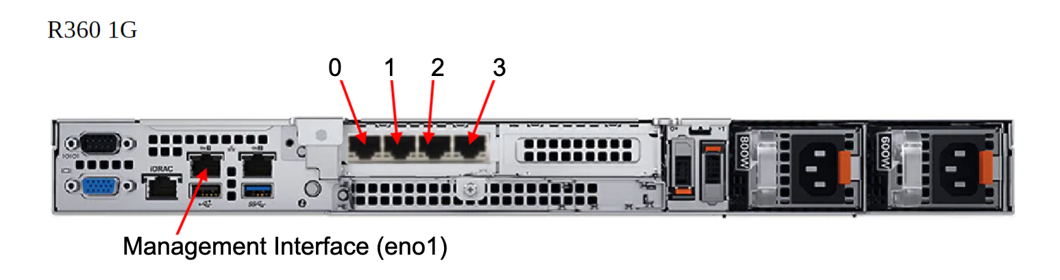
-
High-speed four-port classic iSensor (PER630,PER640):
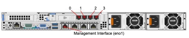
-
Standard four-port classic iSensor (PER6615):
-
High-speed eight-port classic iSensor (PER630,PER640):

-
High-speed 10Gb two-port classic iSensor (PER630,PER640):
-
High-speed 10Gb four-port classic iSensor (PER630,PER640):
-
High-speed 10Gb four-port classic iSensor (PER6615):
Bridges
When classic iSensors are inline with your network, monitoring ports combine to create a bridge. The following table maps the interfaces to bridges.
| Bridge | Interfaces |
|---|---|
| br0 | 0, 1 |
| br1 | 2, 3 |
| br2 * | 4, 5 |
| br3 * | 6, 7 |
System specifications
| Feature | Purpose | Form factor | Rack support | Power supplies | Heat dissipation | NIC |
|---|---|---|---|---|---|---|
| Standard (PER320) | IDS/IPS appliance | 1U rack | Dell A7 Static ReadyRails (default) Dell A8 Sliding ReadyRails (optional) | Hot-plug redundant power supplies (350 watts each) | 1356 BTU/hr maximum | 4-port copper Gb adapter; management interface; hardware fail-open |
| Standard (PER330) | IDS/IPS appliance | 1U rack | Dell A7 Static ReadyRails (default) Dell A8 Sliding ReadyRails (optional) | Hot-plug redundant power supplies (350 watts each) | 1357 BTU/hr maximum | 4-port copper Gb adapter 4-port fiber Gb adapter management interface hardware fail-open |
| High Speed (PER630) | IDS/IPS appliance | 1U rack | Dell A7 Static ReadyRails (default) Dell A8 Sliding ReadyRails (optional) | Hot-plug redundant power supplies (495 watts each) | 1908 BTU/hr maximum | 4/8-port copper Gb adapter 4-port fiber Gb adapter 2/4-port fiber 10Gb adapter management interface hardware fail-open |
| High Speed (PER640) | IDS/IPS appliance | 1U rack | Dell A7 Static ReadyRails (default) Dell A8 Sliding ReadyRails (optional) | Hot-plug redundant power supplies (495 watts each) | 1908 BTU/hr maximum | 4/8-port copper Gb adapter 4-port fiber Gb adapter 2/4-port fiber 10Gb adapter management interface hardware fail-open |
Fiber connection information
This section provides information on the physical connection requirements for the classic iSensor's fiber network interface cards. Note that we don't provide the required fiber cable(s) as part of the classic iSensor shipment.
Two-port 10Gb fiber
The 10Gb classic iSensor fiber card is only offered in conjunction with the high-speed classic iSensor (PER630/640) models.
- Port Quantity: Dual
- Connector Type: Lucent Connector (LC)
- Fail-open and/or Hardware Bypass: Supported
- Interface Data Transfer Rate: 10.3125 GBd
- Fiber Type: Multimode
- Wavelength: 850 nm
- Optical Output Power: Typical: -3.1 dBm; Maximum: -7.3 dBm
- Optical Receive Sensitivity: Typical: -15.37 dBm; Maximum: -11 dBm
Note
If using the two-port 10Gb fiber card on a non-high-speed classic iSensor, inspection throughput is limited to 3.5Gbps.
Four-port 10Gb fiber
The 10Gb classic iSensor fiber card is only offered in conjunction with the high-speed classic iSensor (PER630/640) models.
- Port Quantity: Quad
- Connector Type: Lucent Connector (LC)
- Fail-open and/or Hardware Bypass: Supported
- Interface Data Transfer Rate: 10.3125 GBd
- Fiber Type: Multimode
- Wavelength: 850 nm
- Optical Output Power: Minimum: -7.3 dBm
- Optical Receive Sensitivity: Maximum: -11 dBm
Note
If using the four-port 10Gb fiber card on a non-high-speed classic iSensor, inspection throughput is limited to 3.5Gbps.
Four-port 1Gb fiber
- Port Quantity:Quad
- Connector Type: Lucent Connector (LC)
- Fail-open and/or Hardware Bypass: Supported
- Interface Data Transfer Rate: 10.3125 GBd
- Fiber Type: Multimode
- Wavelength: 850 nm
- Optical Output Power: Typical: -6.0 dBm (TX -Switch Norma - Fiber - LC/LC); Minimum: -10.9 dBm
- Optical Receive Sensitivity: Typical: -20 dBm; Maximum: -15.6 dBm
Note
If using the four-port 1Gb fiber card on a non-high-speed classic iSensor, inspection throughput is limited to 3.5Gbps.
Classic iSensor deployment considerations
During the registration of your classic iSensor, you must determine the implementation that best serves your organization. To aid in making these decisions, review the following options and determine what will be needed prior to the registration process.
Interface configuration
Decide if the interface configuration should be set to auto-negotiate or hardcoded. If hardcoded, decide the speed and duplex settings.
Note
We recommend a crossover cable between a classic iSensor and layer 3 devices, such as routers and firewalls. Auto MDIX will allow for straight through cables to be used between the classic iSensor and layer 3 devices in most cases, but both devices must be configured to auto negotiate speed and duplex. If any side is hard coded, then a crossover cable is required. A straight through cable is required between a classic iSensor and layer 2 devices, such as switches. These requirements are necessary to facilitate the fail open functionality.
Traffic processing mode
You can place your classic iSensor in one of these traffic processing modes:
- Inline-active mode (IPS): The recommended mode for your classic iSensor. All traffic passes through the classic iSensor with network traffic being blocked if determined to be malicious by the signature set.
- Inline-passive mode (IDS): All traffic passes through the classic iSensor and is inspected for alerting. The device will only alert to malicious traffic but won't block it. This is also known as inline-sniffing.
- Sniffer mode (IDS) (non-inline monitor): The network segments to be monitored are spanned to the classic iSensor for inspection, but no traffic is blocked.
Home net
The home net is a network or list of networks that are important to you, and that you wish to protect with the classic iSensor. The classic iSensor uses the defined home net to determine the traffic that will be inspected. These networks are stored as a variable on the classic iSensor called the $HOME_NET. Specifying the correct home net is extremely important to ensure proper coverage of your network.
External net
The external net is the network you want to protect the home net from. There are two general options when setting the external net on the classic iSensor:
!$HOME_NETspecifies networks not defined by the homenet, which is the traditional configuration.Anyspecifies all networks.
If there is a large amount of home-net-to-home-net traffic being seen by the classic iSensor, the external net should be set to !$HOME_NET to reduce false positives.
Setting the external net to !$HOME_NET doesn't limit the visibility of lateral movement. The Sophos Counter Threat Unit™ (CTU) writes all of our signatures with directionality in mind. Signatures that are written for vulnerabilities that can be used for lateral movement are written to look for any to HOME_NET traffic.
Proxy Servers
Proxy servers must be accounted for during the classic iSensor deployment. We must know if you have any proxy servers in the monitored environment, if they are transparent or active (clients are forced through the proxy via browser configuration) proxies, what port number the client browsers connect to the proxy on if active, and the IP address of the proxy.
HTTP ports
After you define any proxy servers, if any are active, record the port number used by clients when proxying through the active proxy in the HTTP ports setting. This is used to instruct the classic iSensor that HTTP traffic is expected on the specified ports and to apply all HTTP signatures to the traffic. If you don't have any proxy servers in your environment, but you have HTTP traffic traversing your network on a port other than the default ports, ensure they are added to the HTTP ports setting for proper traffic inspection.
The default HTTP ports variable is:
[80,81,88,311,383,591,593,901,1220,1414,1741,1830,2301,2381,2809,3037,3128,3702,4343,4848,5250,6988,7000,7001,7144,7145,7510,7777,7779,8000,8008,8014,8028,8080,8085,8088,8090,8118,8123,8180,8181,8243,8280,8300,8800,8888,8899,9000,9060,9080, 9090,9091,9443,9999,11371,34443,34444,41080,50002,55555]
Signature sets
There are three signature set policies you can use with your classic iSensor.
Balanced
The balanced policy offers a mix of increased security coverage while still aiming to provide minimal impact to legitimate traffic.
-
Traffic dropped by the balanced policy includes but isn't limited to the following examples:
- Malware seen within the current threat landscape.
- Traffic aimed at exploiting high-severity vulnerabilities in both widespread and lesser-used software.
-
Traffic that generates detections, but isn't dropped, includes but isn't limited to the following examples:
- Traffic commonly associated with reconnaissance attempts/the noise of the internet.
- Traffic that triggers lower fidelity signatures.
- Traffic related to questionable activities, such as torrent use.
Security
The security policy provides the highest security coverage feasible, while aiming to limit impact to legitimate enterprise traffic. The security policy leans towards stronger security over connectivity, thus it accepts a higher false positive rate in order to provide increased coverage.
Traffic dropped by the security policy includes but isn't limited to the following examples:
- Malware seen within the current threat landscape.
- Traffic aimed at exploiting vulnerabilities in both widespread and lesser-used software for high- and medium-severity vulnerabilities.
- Traffic commonly associated with reconnaissance attempts/the noise of the internet.
- Generic signatures to prevent common attacks, such as SQL injection and Cross-Site Scripting attacks.
- Traffic related to questionable activities, such as torrent use.
Connectivity
The connectivity policy protects against the most severe threats, which have the highest risk within an enterprise environment. It provides minimal impact to legitimate traffic.
-
Traffic dropped by the connectivity policy includes but isn't limited to the following examples:
- Malware seen within the current threat landscape.
- High threat exploit attempts against known vulnerabilities in widespread software or software actively being exploited in the wild.
-
Traffic that generates detections, but isn't dropped, includes but isn't limited to:
- Threats identified by signatures that protect against a variety of medium threat events in lesser-used applications.
Signatures that generate more noise are disabled by default.
Physical classic iSensor deployment scenarios
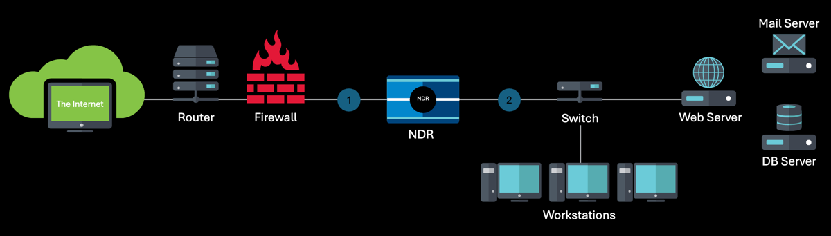
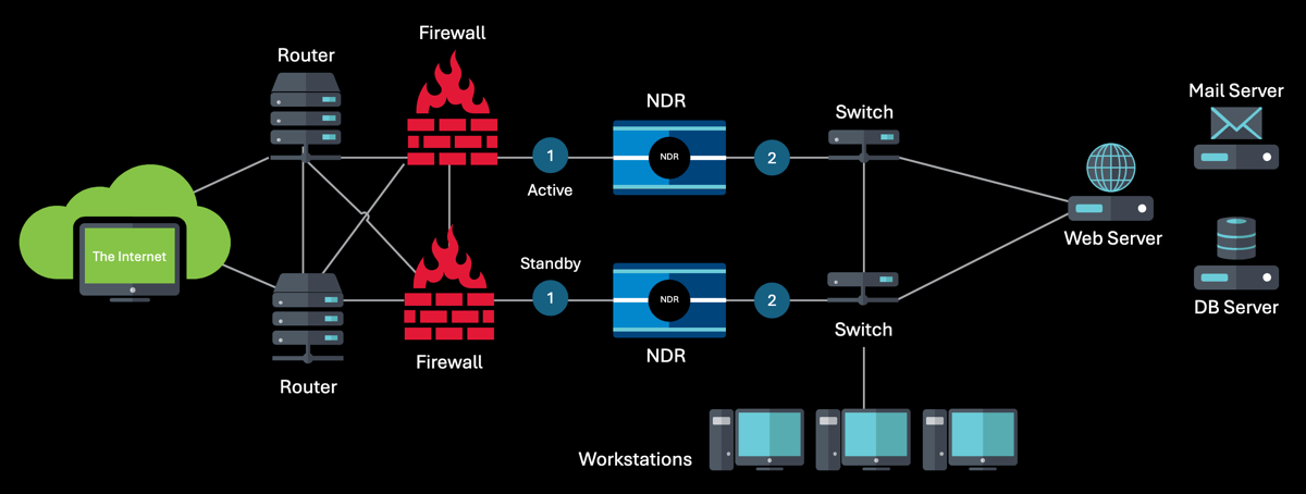
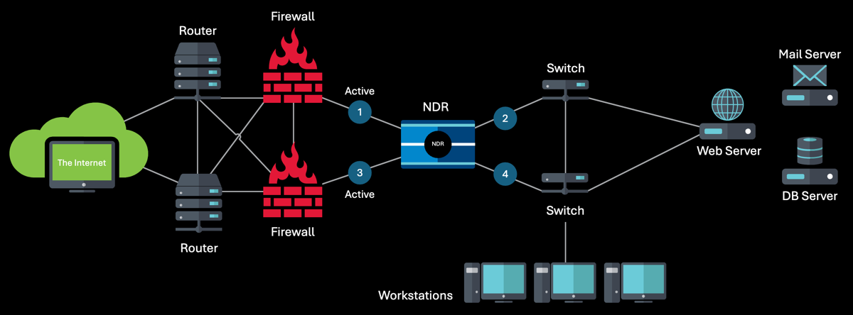
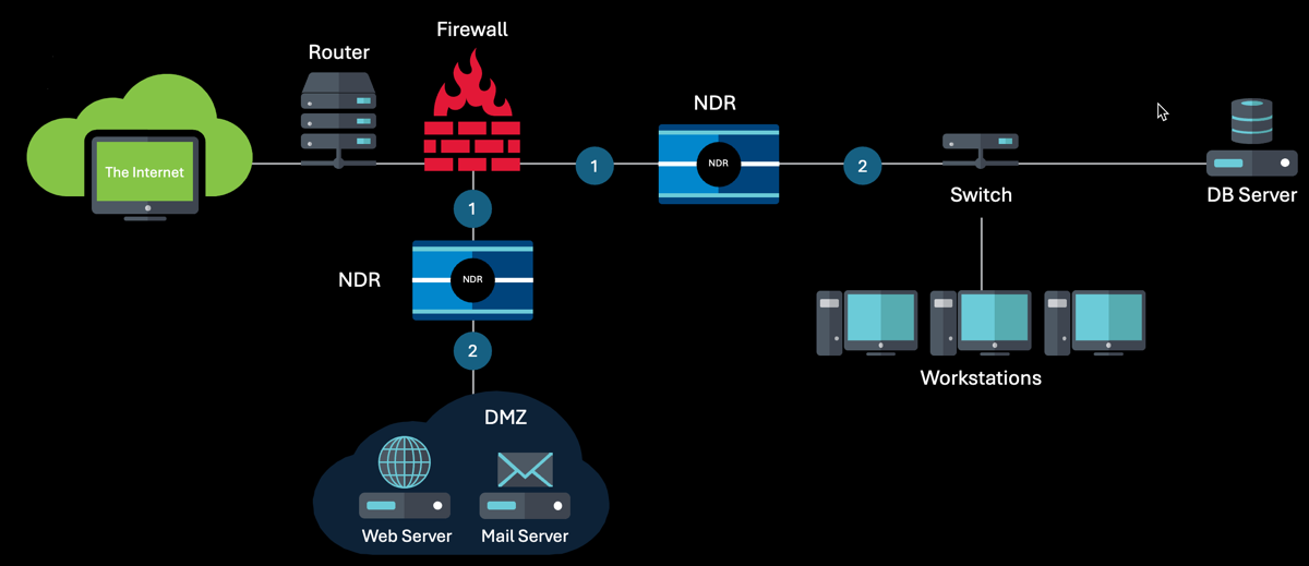
The following images show installation scenarios that represent common internal deployments that adhere to best practices. We don't recommend deploying the classic iSensor external to the firewall due to detection concerns and masking (hide NAT) of internal assets. Alternative classic iSensor deployment scenarios should be reviewed, approved, and documented with your installation team.
-
Internal inline: This image shows the classic iSensor in an internal inline deployment.
-
HA active/standby internal inline: This image shows the classic iSensor in a high-availability active/standby internal inline deployment.
-
HA active/active internal inline: This image shows the classic iSensor in a high-availability active/active internal inline deployment.
-
Internal DMZ inline: This image shows the classic iSensor in an internal DMZ inline deployment.
-
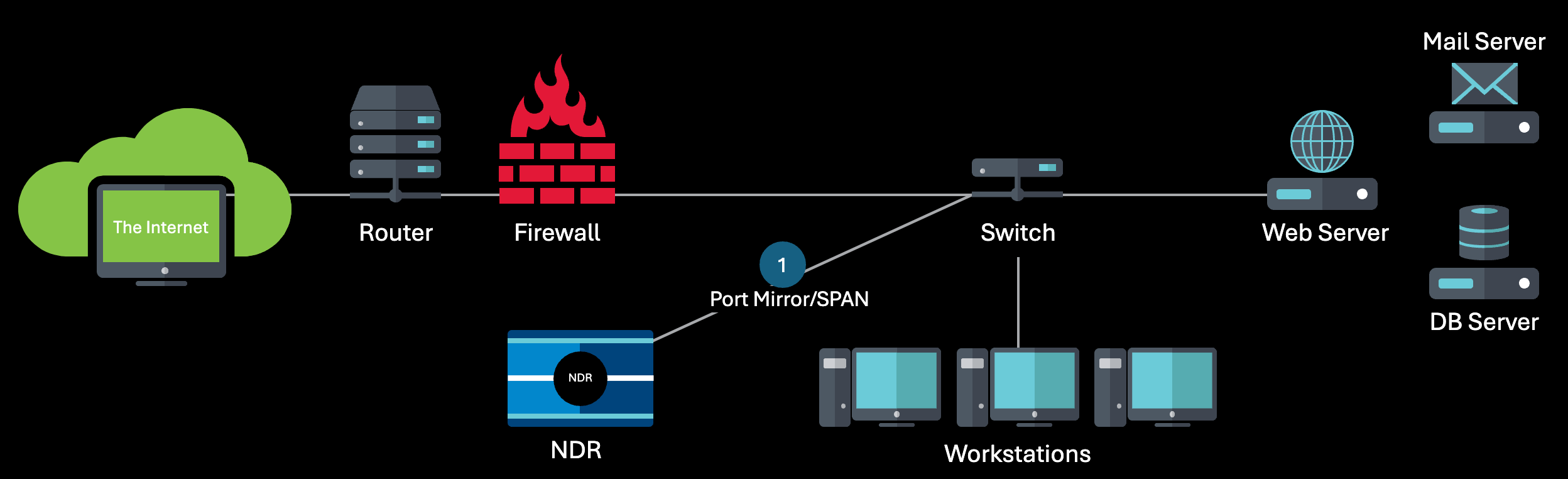
Internal sniffer: This image shows the classic iSensor in an internal sniffer deployment.
-
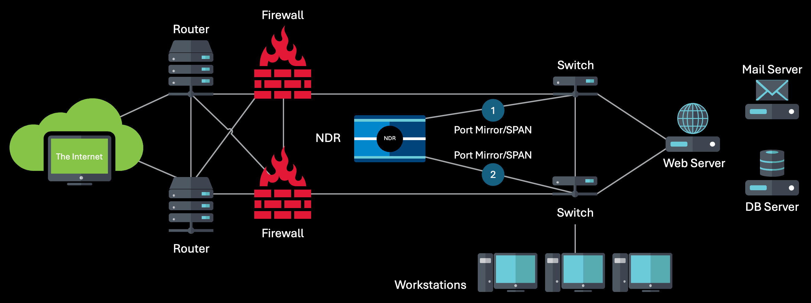
HA internal sniffer: This image shows the classic iSensor in a high-availability internal sniffer deployment.
-
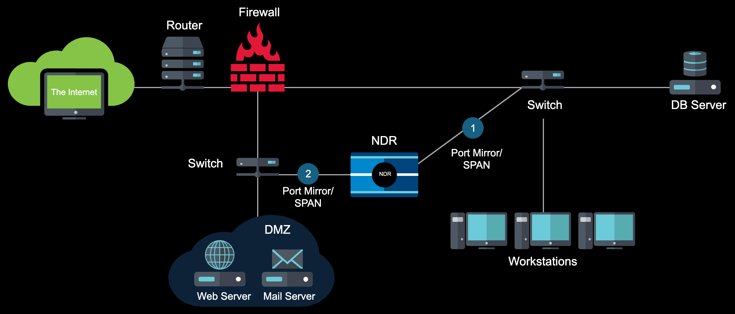
Internal DMZ sniffer: This image shows the classic iSensor in an internal DMZ sniffer deployment.
Registration preparation
Before you begin the installation of your classic iSensor, prepare the following important pieces of information that you will be prompted for during the installation process:
- Device hostname
- Classic iSensor registration key: If you don't have this already, contact your onboarding project manager to obtain the key.
- Classic iSensor mode that you wish to use: At this time, you should have already worked with a Sophos representative to identify the best solution for you. You must select one of the three modes during the installation process.
- IP address to assign to your classic iSensor: If you plan to use a static IP for your classic iSensor, have your IP address, network mask, and gateway address ready for entry during the installation process. These values should have been provisioned by your network team for use by the classic iSensor.
Configuration and registration
To begin installation of your classic iSensor, do as follows:
- Connect the classic iSensor management port to your network.
- Connect a monitor and keyboard to your classic iSensor.
- Turn on your classic iSensor. The classic iSensor Configuration Wizard displays.
- At the initial screen, the classic iSensor automatically attempts to detect if the management port is connected. If No interface detected shows, verify the management interface cable is connected and fully seated. Once done, select Yes to retry the interface detection.
- On the next prompt, select Configure Static and then enter your IP, netmask, and gateway information.
- The classic iSensor attempts to ping its gateway to verify the information is valid. If a ping failure is expected, select Ignore to continue with the registration process.
- Confirm the network configuration by selecting the Use option.
- After you confirm the network configuration, select the classic iSensor mode for your device and then select OK to continue.
-
Enter the registration key you obtained from your onboarding project manager. See the following note to download a specific classic iSensor version, if required. Otherwise, select OK.
(Optional) Specify iSensor version.
If your compliance framework requires your classic iSensor version to be controlled, you may select a specific classic iSensor version to download.
After you've entered your registration key, select Classic iSensor Version, enter your desired classic iSensor version, and select OK.
-
If you didn't select the option to enter a specific classic iSensor version, select whether to disable automatic software updates. These updates include minor OS patches that won't disrupt inspection or network connection(s). We recommend you select No to enable updates.
-
The classic iSensor now downloads software and configures itself.
You have now successfully registered and configured your classic iSensor.
Network reconfiguration
Use the classic iSensor CLI to modify the network configuration when working with support.
Warning
This command should only be used while working with support to change the network configuration of the classic iSensor. Changes made locally have direct impact on the monitoring and management of the device and could lead to a service outage if not directed by a member of support.
Do as follows:
-
From the console of the classic iSensor, connect a monitor and keyboard to the system.
If there is no output present, select Enter to wake the console.
-
Use the
setcommand with the following options to make changes to your network configuration:set dhcp [enable|disable]set gateway <ip>set ip <ipv4> <netmask> <gateway>set netmode [passive|ips|monitor]
Registration error codes
The following error codes may be seen during configuration or registration. Review the description for details.
| Error code | Description |
|---|---|
| 20 | User cancelled the process of setting the network configuration. |
| 21 | User cancelled the process of selecting the classic iSensor mode. |
| 22 | User cancelled the process of setting up a registration key. |
| 23 | The policy obtained isn't a valid XML file. |
| 24 | The policy contains an empty VPN password field. |
| 25 | VPN connection failed - user decides not to retry. |
| 26 | Unable to retrieve RCMS certificates. |
| 27 | Certificate tar file missing /var/mqm/ssl/Key.sth file. |
| 28 | CIP server information is missing from the policy (Certinit.config). |
| 29 | Unable to obtain UIN - Server provided an invalid response. |
| 30 | Unable to obtain UIN - Server provided no response. |
| 31 | Imagetools configuration is missing the classic iSensor Version. |
| 32 | Image MD5Sum didn't match what the server MD5Sum. |
| 33 | Image installation failed (instimage.barebone). |