NDR 5500 hardware specifications
The NDR 5500 is a physical Sophos NDR appliance based on the Sophos XGS 5580 hardware platform. It uses NDR-specific firmware.
Platform
The base model for the NDR 5500 appliance is the Sophos XGS 5580.
The NDR 5500 has the following differences from the base model:
- Two 2 TB SSDs instead of two 480 GB SSDs
- NDR firmware and branding
Processing and memory
| Item | Specification |
|---|---|
| CPU | AMD EPYC 4005 series (Zen 5), 16 cores / 32 threads, 3.0–3.4 GHz base, up to 5.4 GHz boost (actual sustained boost may be lower) |
| NPU | Marvell, A72-based, 24 cores, 1.8 GHz, 16 GB memory |
| Memory | 64 GB total, using 2 memory channels at 5600 MT/s per channel |
Storage
| Item | Specification |
|---|---|
| Primary storage | Two 2 TB removable NVMe SSDs, software RAID |
| Boot storage | One 32 GB eMMC, non-removable |
Network ports
The NDR 5500 base unit ships with the following fixed network ports:
- F1-F4: Four SFP28 fiber ports, reserved for future use.
- LAN 1-8: Eight 2.5GbE copper ports. Port 1 also functions as the management port.
- EXTP: One dedicated copper port.
The base unit also includes two expansion bays that support the following Flexi Port modules:
- Four-port GE copper module with two bypass pairs.
- Two-port 10GE fiber LC module with one bypass pair.
The following diagram shows the ports used for the serial connection, internet connectivity to Sophos Fusion, optional local management, and network traffic capture.
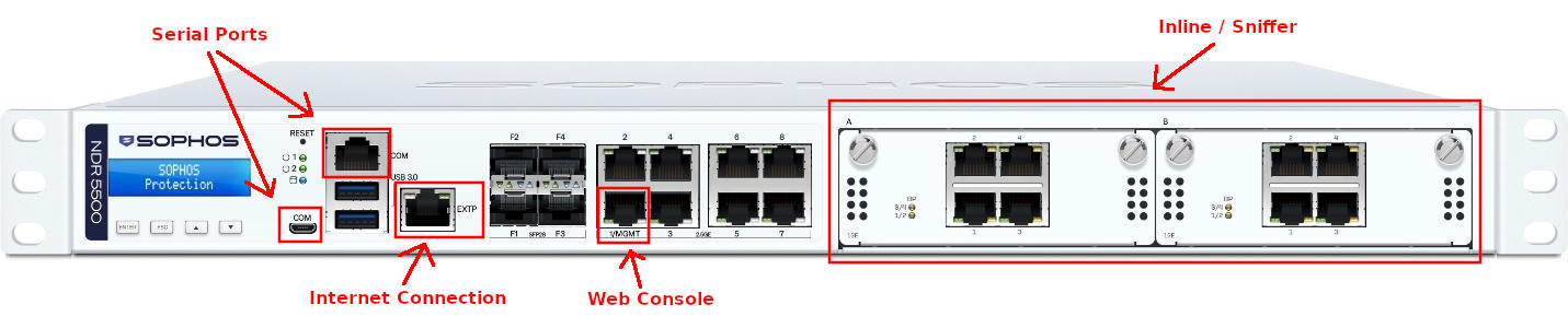
Sophos NDR currently doesn't use Ethernet or fiber ports not shown as active connections in the diagram. The expansion-module ports capture network traffic inline or out of band from a SPAN or mirror port or network TAP.
The mode you select in Sophos Fusion determines how the capture interfaces handle traffic:
- Out-of-band: NDR, NDR+IDS, and IDS modes inspect a copy of network traffic. You can connect each capture port independently to a SPAN or mirror port or network TAP. This is also referred to as a sniffer deployment.
- Inline: NDR+IPS Active, NDR+IPS Passive, IPS Active, and IPS Passive modes inspect traffic that passes through the appliance. Connect the capture ports in the bypass pairs defined by the Flexi Port module.
All capture ports on the appliance use the same traffic mode. You can't use some capture ports inline and others out of band.
Port wiring
The Flexi Port module determines how many traffic feeds or inline network links you can connect to the NDR 5500:
| Flexi Port configuration | Out-of-band | Inline |
|---|---|---|
| Two four-port GE copper modules | Up to eight capture feeds | Up to four bridge pairs |
| Two two-port 10GE fiber LC modules | Up to four capture feeds | Up to two bridge pairs |
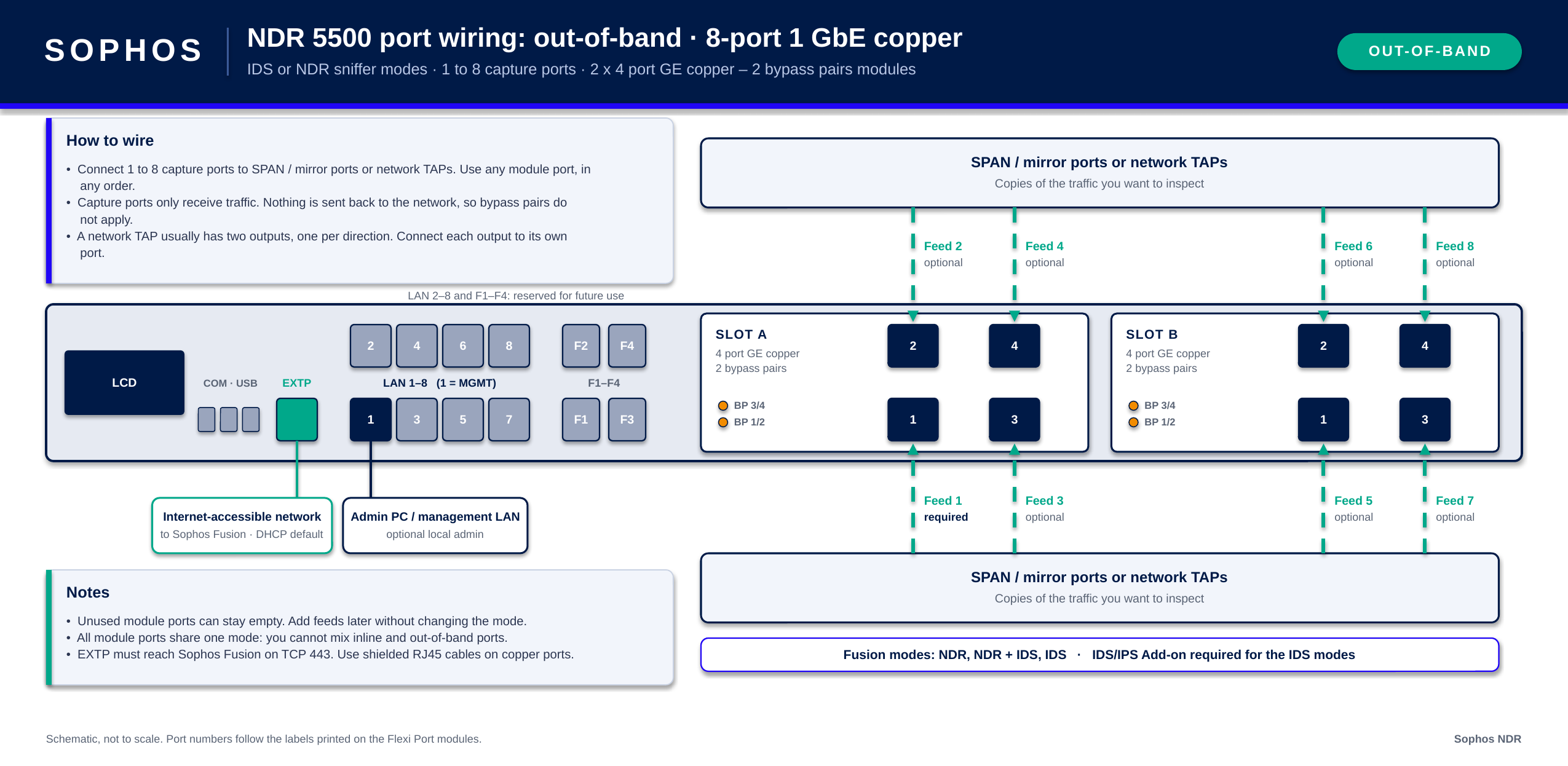
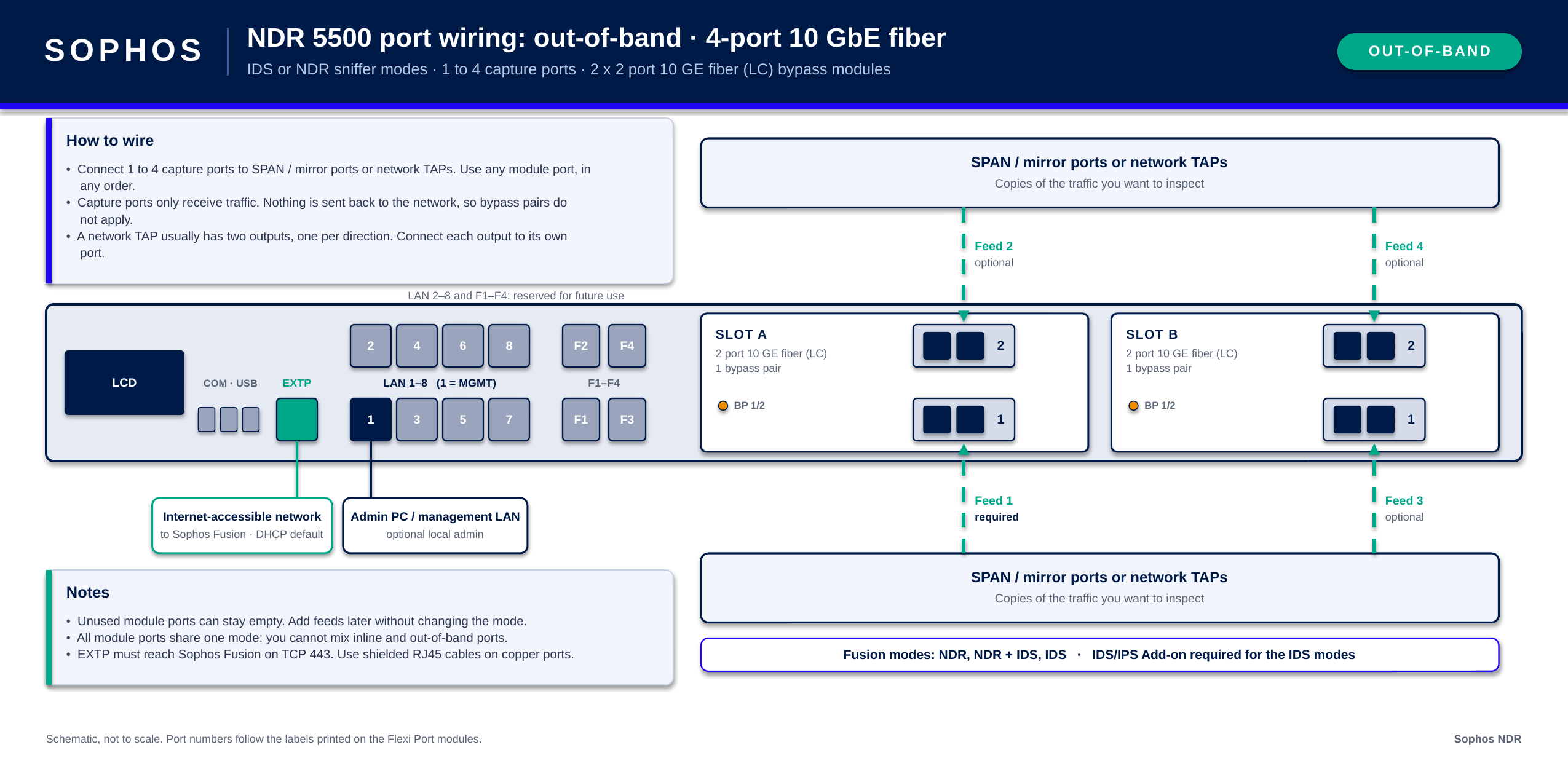
For out-of-band deployments, capture ports receive copies of network traffic and don't forward traffic back to the network. The ports don't need to be connected as bypass pairs.
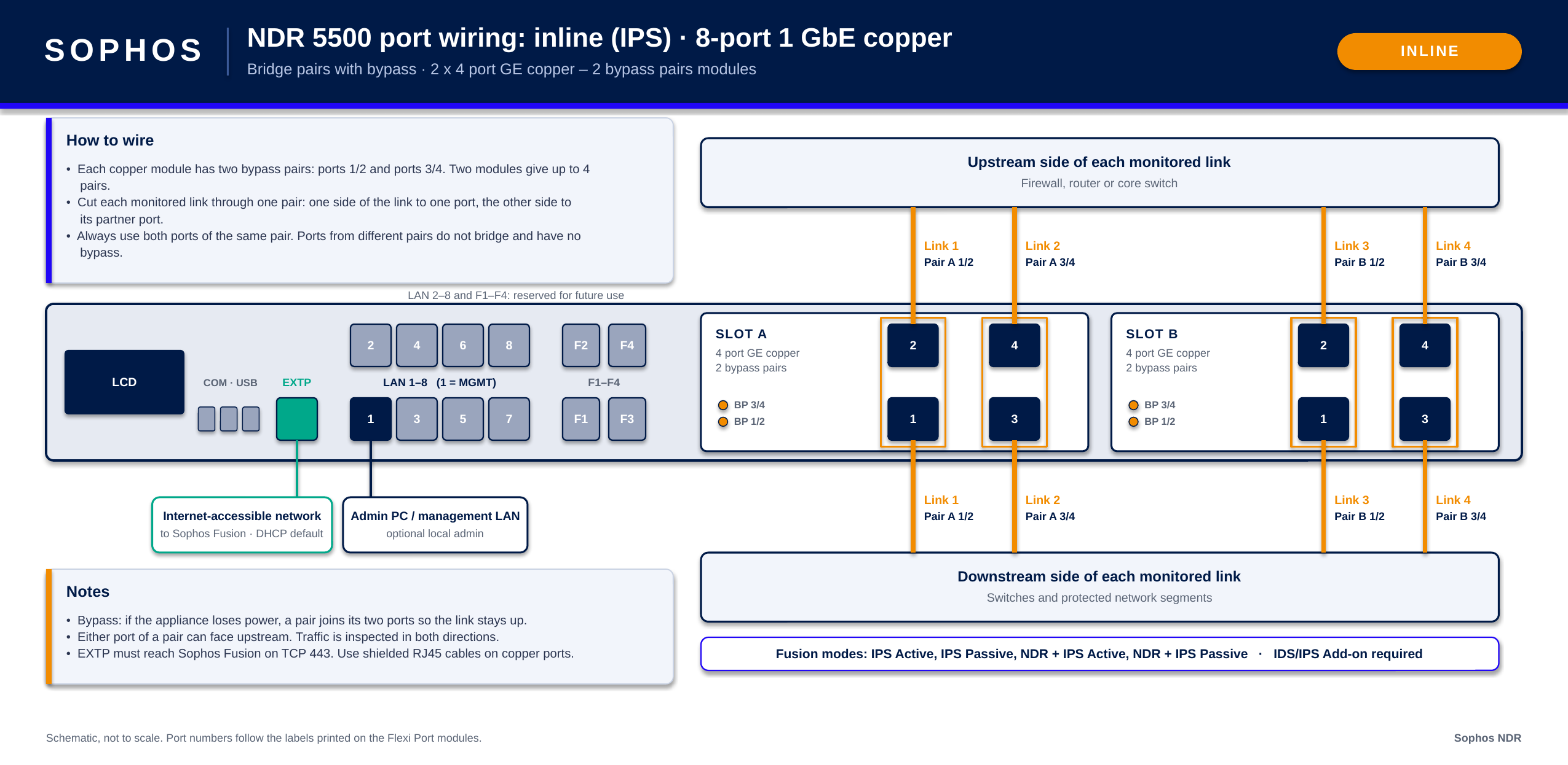
For inline deployments, each monitored network link uses both ports in a bypass pair. Don't combine ports from different bypass pairs to create an inline bridge.
GE copper, out-of-band
The example below shows out-of-band wiring with two four-port GE copper modules. You can connect up to eight independent traffic feeds from SPAN or mirror ports or network TAPs. Unused capture ports can remain disconnected.
GE copper, inline
The example below shows inline wiring with two four-port GE copper modules. Each module provides two bypass pairs, for a total of up to four inline bridge pairs. Each monitored network link must use both ports from the same bypass pair.
10GE fiber, out-of-band
The example below shows out-of-band wiring with two two-port 10GE fiber LC modules. You can connect up to four independent traffic feeds from SPAN or mirror ports or network TAPs. Unused capture ports can remain disconnected.
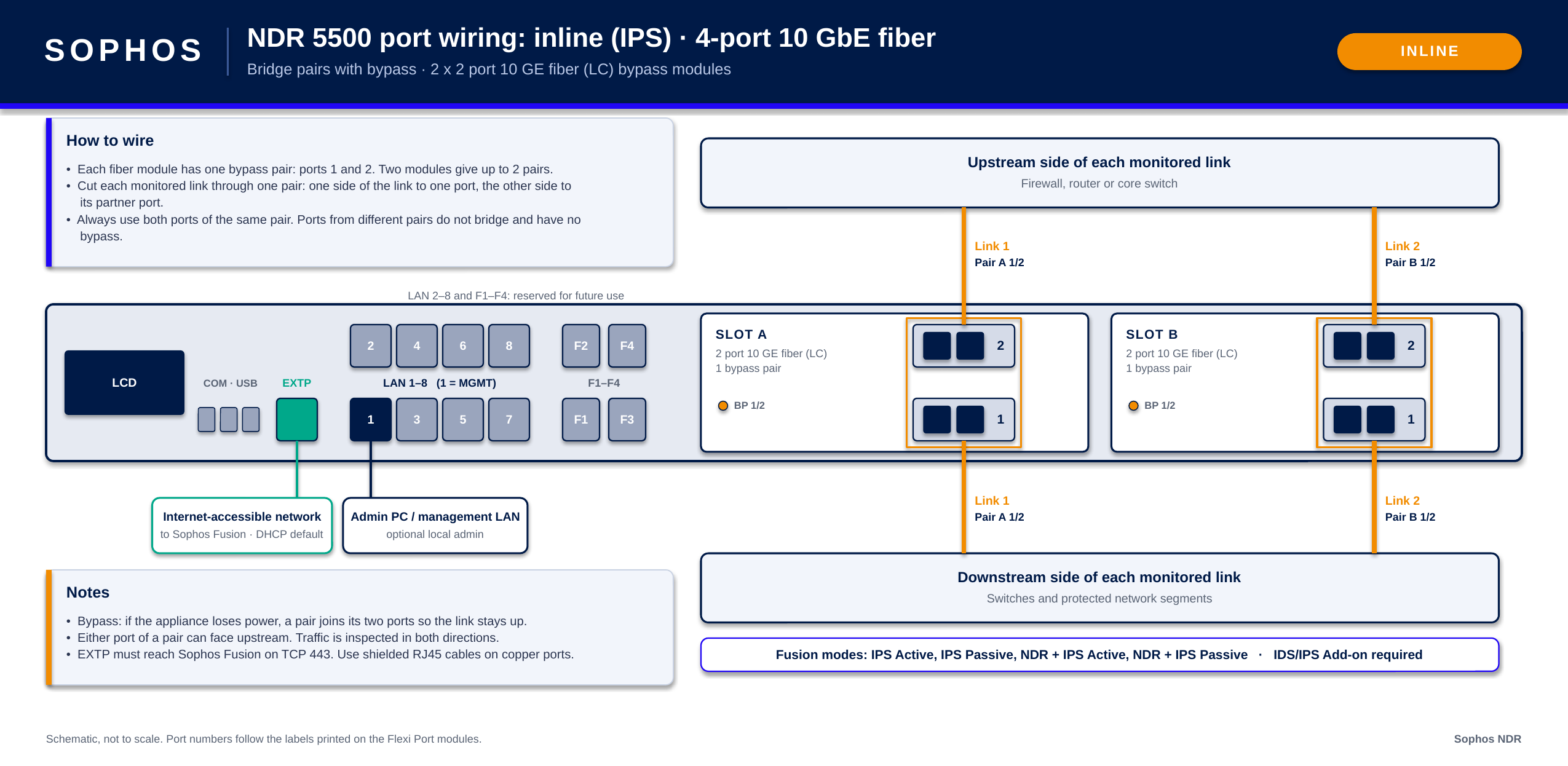
10GE fiber, inline
The example below shows inline wiring with two two-port 10GE fiber LC modules. Each module provides one bypass pair, for a total of up to two inline bridge pairs. Each monitored network link must use both ports from the same bypass pair.
Chassis features
| Item | Included |
|---|---|
| Baseboard management controller (BMC) | No |
| Display | Yes |
| TPM | Yes |
| Rack mounting | Yes |
| Power supply | Dual power supply |