Deploy the firewall in an active-active HA cluster
You can deploy two Sophos Firewalls in an active-active high availability (HA) cluster in Azure with load balancing. The deployment uses the Azure standard load balancer with its HA ports feature to provide both inbound and outbound load distribution.
Active-passive deployments aren't supported.
This deployment uses an Azure template to automatically configure the required routes for the load balancers.
Note
This template uses a /16 subnet for the virtual network (vNet) and /24 subnets for the LAN and WAN networks. If you plan to use different subnet sizes, contact your Sophos account manager before making any changes to the provided template.
Network diagram
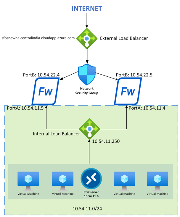
The network diagram shows two firewalls connected to a load balancer on the external (internet-facing) network and another load balancer on the internal network. This setup provides load balancing for both inbound and outbound traffic, ensuring high availability and optimized performance.
Requirements
You must have one of the following licenses:
- Bring Your Own License (BYOL): A valid license is required for each firewall.
- Pay As You Go (PAYG)
You must verify that your firewall and security group configurations allow access to TCP ports 4444 and 3128. The load balancers use these ports for external and internal health checks.
Note
If you need to use different ports, update the load balancer health check settings after deployment. When changing ports, make sure that internal and external health checks use different ports to prevent conflicts.
Deployment
To deploy the firewall in an active-active HA cluster, do as follows:
- Sign in to the Microsoft Azure portal.
- In a separate browser tab, go to Sophos Firewall active-active HA deployment template.
- Click Deploy to Azure to launch the template in the Azure portal.
-
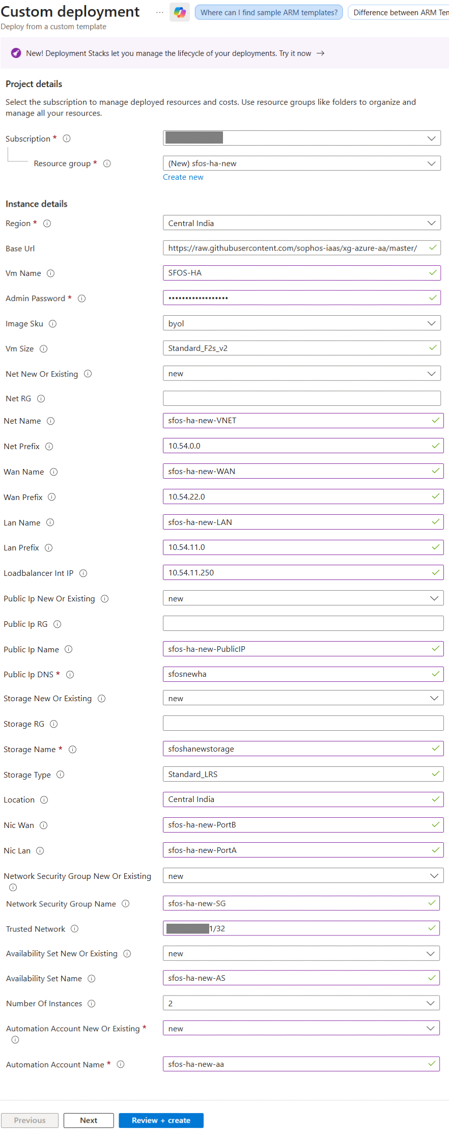
Configure the following settings:
Setting Value Project details Subscription Select your Azure subscription. Resource group Click Create new, enter a name, then click OK. Instance details Region Select the deployment region. Base URL Don't change the URL. VM name Enter a name for the virtual machine. Admin password Create a strong, complex password and store it securely. You'll need this to sign in for the first time. Image SKU Select BYOL if you're using a purchased license.
Select PAYG-new if you'll pay through Azure billing.
VM size Enter a size that supports at least two NICs. For example,
Standard_F2s_v2.Net new or existing Select new for a new vNet.
Select existing for an existing vNet.
Net RG Enter the resource group of the new or existing network. Net name Enter the name of the new or existing virtual network. Net prefix Enter the network portion of the CIDR block for the new or existing virtual network. The subnet mask is automatically set to /16.WAN name Enter the name of the new or existing frontend WAN subnet. WAN prefix Enter the subnet portion of the CIDR block for the new or existing frontend WAN subnet. The subnet mask is automatically set to /24.LAN name Enter the name of the new or existing LAN subnet. LAN prefix Enter the subnet portion of the CIDR block for the new or existing LAN subnet. The subnet mask is automatically set to /24.Loadbalancer Int IP Enter the IP address of the internal (outbound) load balancer. The IP address must be in the range of the LAN prefix. Public IP new or existing Select new if you want to create a new public IP address.
Select existing if you have an existing public IP address.
Public IP RG Enter the resource group of the new public IP address. We recommend that you use the same resource group as the Net RG. Public IP name Enter the name of the new or existing public IP address. Public IP DNS Enter the DNS name record that will be created in Microsoft's DNS zone.
If you're using an existing public IP address, enter its associated DNS name.
The DNS name must be unique across the entire zone. To ensure uniqueness, include random numbers or characters in the name.
Storage new or existing Select new if you want to create a new storage account.
Select existing if you have an existing storage account.
Storage RG Enter the resource group that contains the new or existing storage account. Storage name Enter the name of the new or existing storage account for the VM disks. Storage type Enter the storage type. For example,
Standard_LRS.Location Enter a custom location or use the resource group's location. NIC WAN Enter the name of the firewall's frontend WAN NIC. NIC LAN Enter the name of the firewall's backend LAN NIC. Network security group new or existing Select new if you want to create a new network security group.
Select existing if you have an existing network security group.
Network security group name Enter the name of the network security group (NSG) for the firewall's WAN NIC. Trusted network Enter the IP address or CIDR network range to use for admin access.
You must set this to
*forany. The Azure automation account uses Azure public IP addresses for the connection. Restricting this causes runbook failure. You can secure the NSG after deployment.Availability set new or existing Select new if you want to create a new availability set.
Select existing if you have an existing availability set.
Availability set name Enter the name of the availability set for the firewalls. Number of instances Select the number of firewalls that you want to deploy in the availability set.
You can deploy a maximum of two firewalls using this template. If required, the maximum value can be modified in the template.
Automation account new or existing Select new if you want to create a new automation account.
Select existing if you have an existing automation account.
Automation account name Enter the name of the automation account for the post-deployment runbook.
Azure Automation accounts are supported only in specific regions. Make sure that you select a supported location. See Products available by region.
-
Click Next.
-
Click Create.
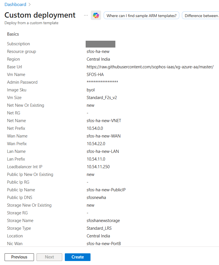
Azure begins deploying two firewalls in an active-active HA cluster, along with inbound and outbound load balancers to manage traffic efficiently. The deployment typically takes 10 to 15 minutes to complete.
Connecting to the firewalls
You can connect to the firewalls using either the web admin console or the Command-Line interface (CLI).
To get step-by-step instructions, click the tab for the firewall access method you want to use.
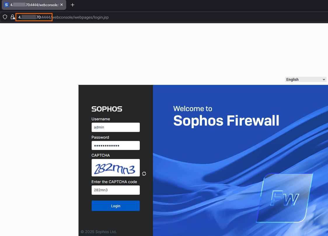
To connect to the firewalls' web admin console, do as follows:
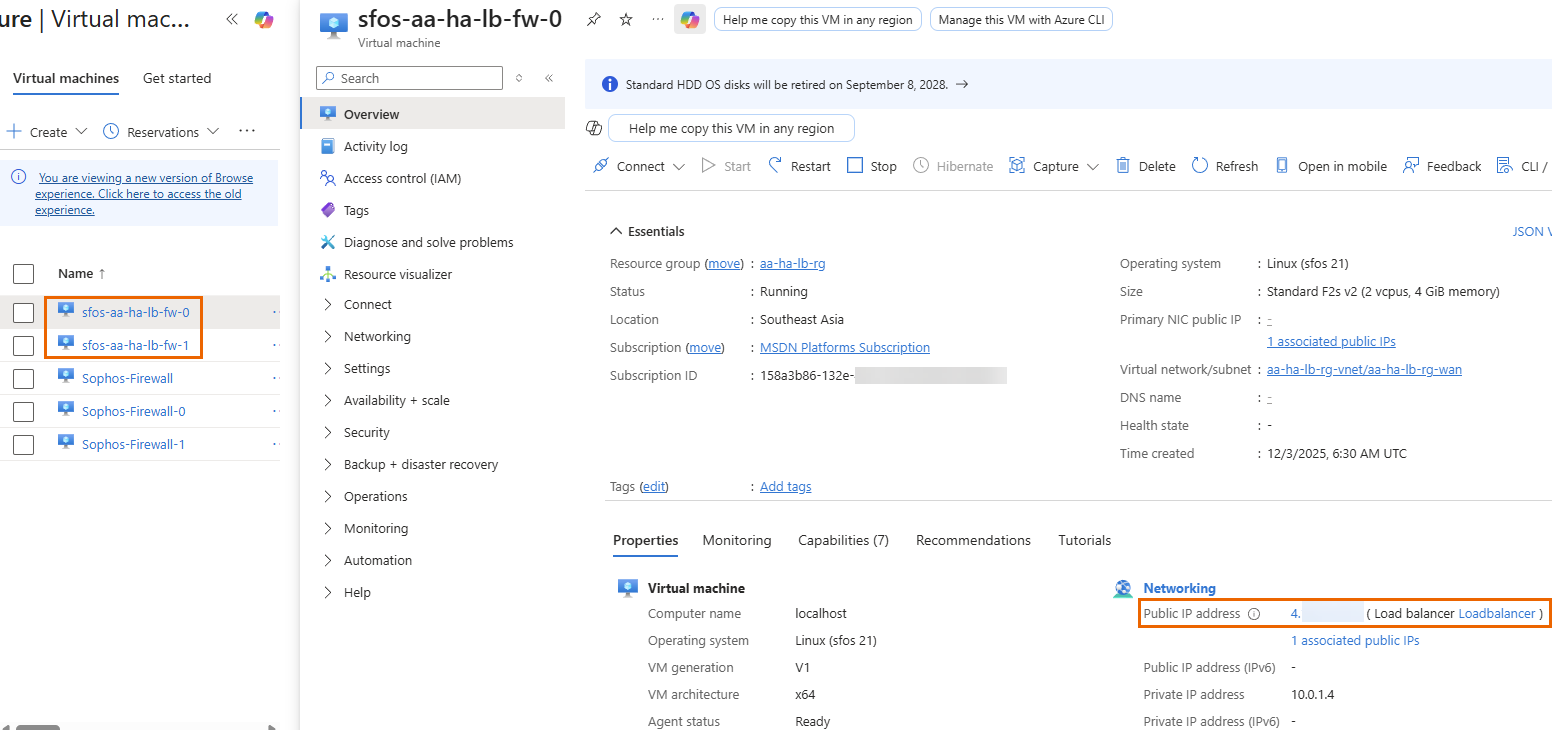
- In the Azure portal, go to Home > Virtual machines.
-
Select one of the deployed firewalls and copy its Public IP address. Repeat the process for the other firewall.
Tip
You can also use the DNS name of the external load balancer.
-
Connect to the firewalls in a new web browser as follows:
- To connect to the first firewall, enter
https://<public IP or DNS name of the external load balancer>:4444. - To connect to the second firewall, enter
https://<public IP or DNS name of the external load balancer>:4445.
- To connect to the first firewall, enter
-
Sign in using the following credentials:
- Username:
admin - Password: Admin password you created during deployment
- Username:
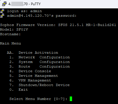
To connect to the firewalls' CLI console, do as follows:
- In the Azure portal, go to Home > Virtual machines.
-
Select one of the deployed firewalls and copy its Public IP address. Repeat the process for the other firewall.
-
To connnect to the firewalls' CLI console, follow the steps in SSH to the firewall using PuTTY.
You must use the following ports:
- First firewall:
2222 - Second firewall:
2223
- First firewall:
-
Sign in using the following credentials:
- Username:
admin - Password: Admin password you created during deployment
- Username:
Registering the firewalls
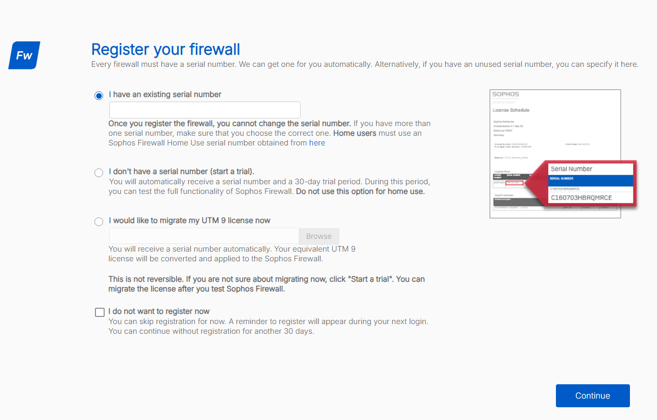
To register the firewalls, do as follows:
- Connect to the first firewall using port
4444, then sign in. See Connecting to the firewalls. -
Select one of the following options:
-
I have an existing serial number:
Select this option if you have a serial number provided by Sophos or your partner, then enter the serial number.
-
I don't have a serial number (start a trial):
Select this option to start a 30-day trial. A serial number is generated automatically.
This option is used in our setup example.
-
-
Click Continue.
-
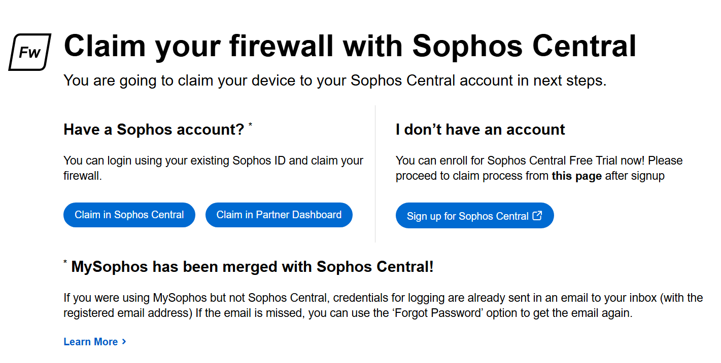
Claim the firewall in Sophos Central by clicking one of the following options:
-
Claim in Sophos Central:
Use this option to claim the firewall with an existing Sophos Central account.
This option is used in our setup example.
-
Claim in Partner Dashboard:
Use this option to claim the firewall through your Partner account.
-
Sign up for Sophos Central:
Use this option to create a new Sophos Central account and claim the firewall.
-
-
Click Claim firewall.
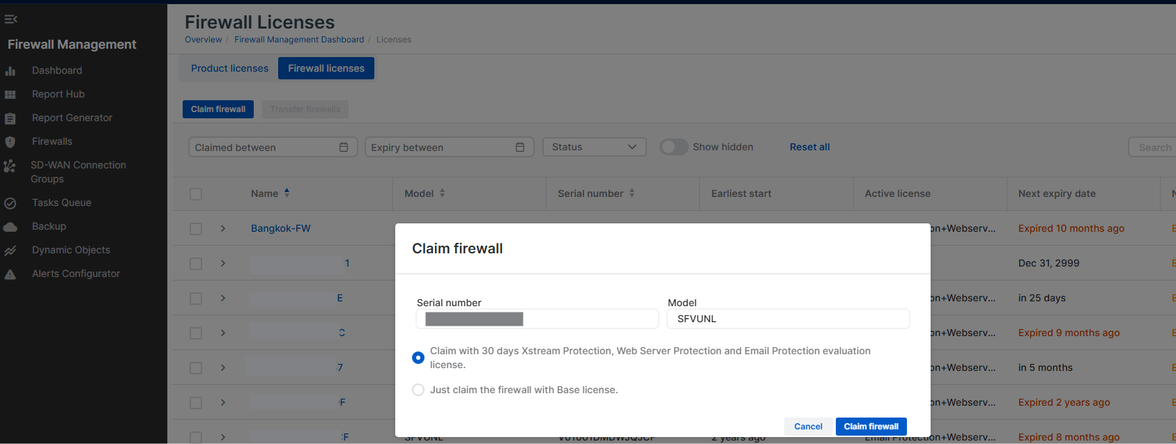
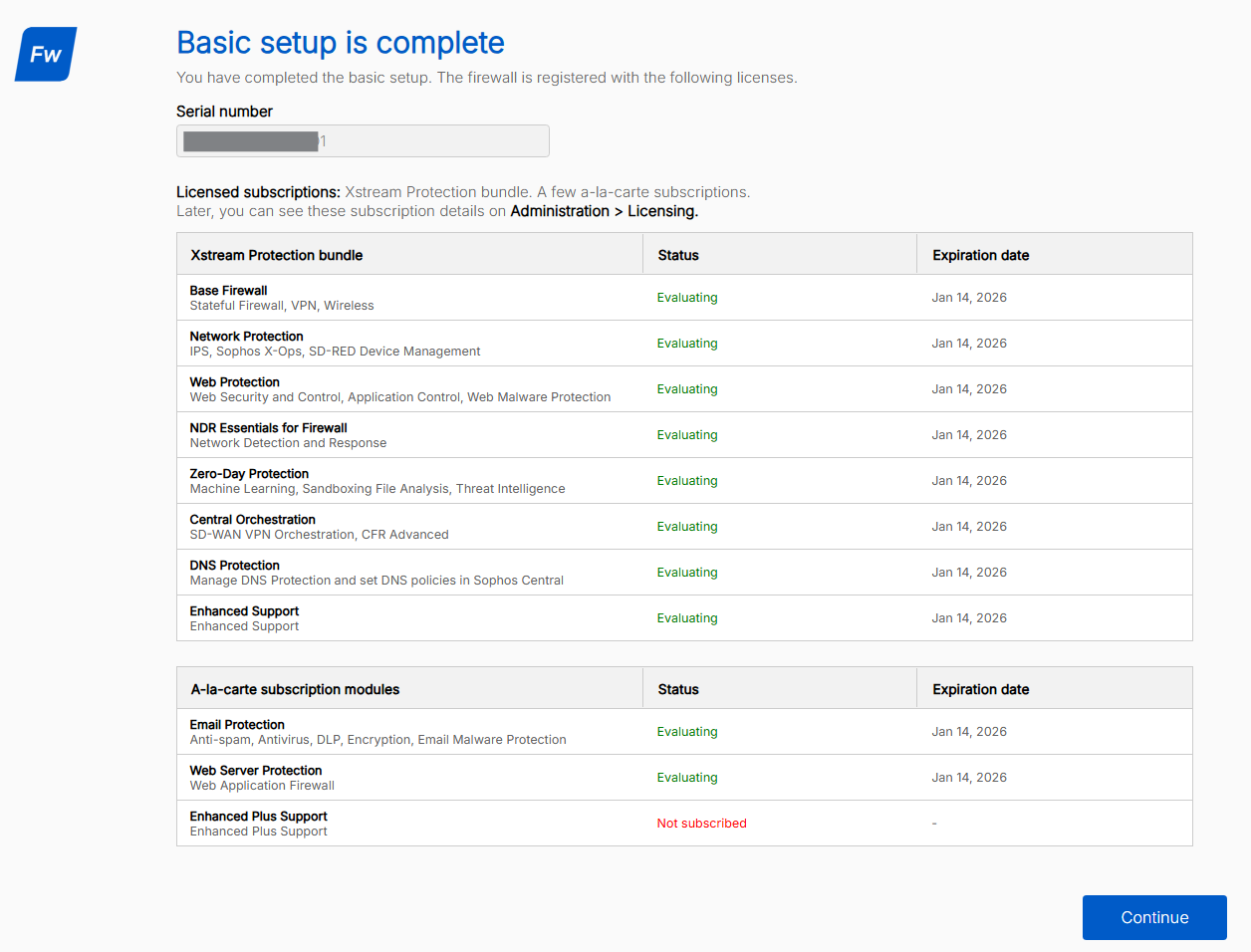
The page shows details such as the serial number, trial subscriptions, and expiration dates.
-
Click Continue.
Repeat these steps for the second firewall.
Configure load balancer health probes
You can configure the load balancer health probes to make sure that traffic flows properly and is distributed by the load balancers.
To configure load balancer health probes, you must create gateways and SD-WAN routes for the external and internal load balancers on both firewalls. Do as follows:
- Connect to the first firewall using port
4444, then sign in. See Connecting to the firewalls. -
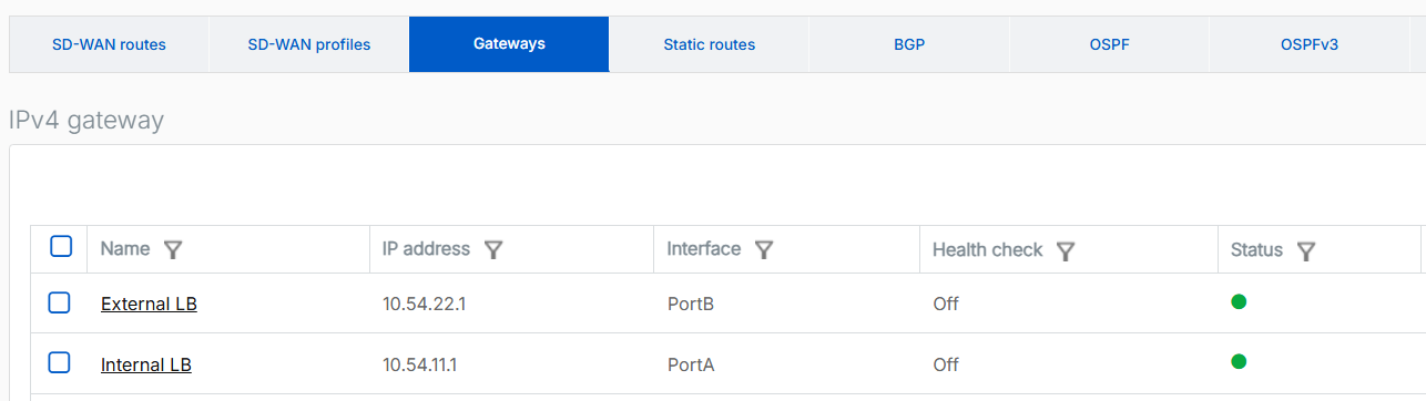
Create a gateway for the internal load balancer as follows:
- Go to Routing > Gateways and click Add.
-
Configure the following settings:
Setting Value Name Enter a name for the internal load balancer gateway. For example, Internal LB.Gateway IP Enter the first IP address of the internal load balancer's subnet.
In this example, it's
10.54.11.1.Interface Select the WAN interface. Zone Select None. -
Turn off Health check.
- Click Save.
-
Create a gateway for the external load balancer as follows:
- Go to Routing > Gateways and click Add.
-
Configure the following settings:
Setting Value Name Enter a name for the external load balancer gateway. For example, External LB.Gateway IP Enter the first IP address of the external load balancer's subnet.
In this example, it's
10.54.22.1Interface Select the WAN interface. Zone Select None. -
Turn off Health check.
- Click Save.
-
Create a route for the internal load balancer probing as follows:
- Go to Routing > SD-WAN routes and click Add.
-
Configure the following settings:
Setting Value Name Enter a name for the internal load balancer route. Route position Select Top. Source networks Remove Any and select the LAN port.
In this example, it's #PortA.
Destination networks Remove Any and click Add new item to create an IP address host for Azure's magic IP address 168.63.129.16.Primary and Backup gateways Select this option. Primary gateway Select the internal load balancer gateway that you created. Route only through specified gateways Select this option. 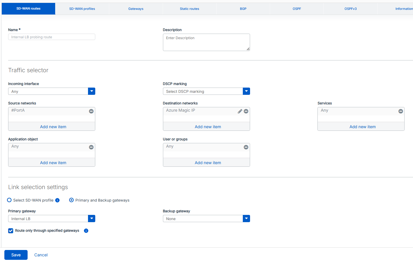
-
Click Save.
-
Create a route for the external load balancer probing as follows:
- Go to Routing > SD-WAN routes and click Add.
-
Configure the following settings:
Setting Value Name Enter a name for the external load balancer route. Route position Selct Top. Source networks Remove Any and select the WAN port.
In this example, it's #PortB.
Destination networks Remove Any and click Add new item to create an IP address host for Azure's magic IP address 168.63.129.16.Services Remove Any and select HTTP. Primary and backup gateways Select this option. Primary gateway Select the external load balancer gateway that you created. Route only through specified gateways Select this option. 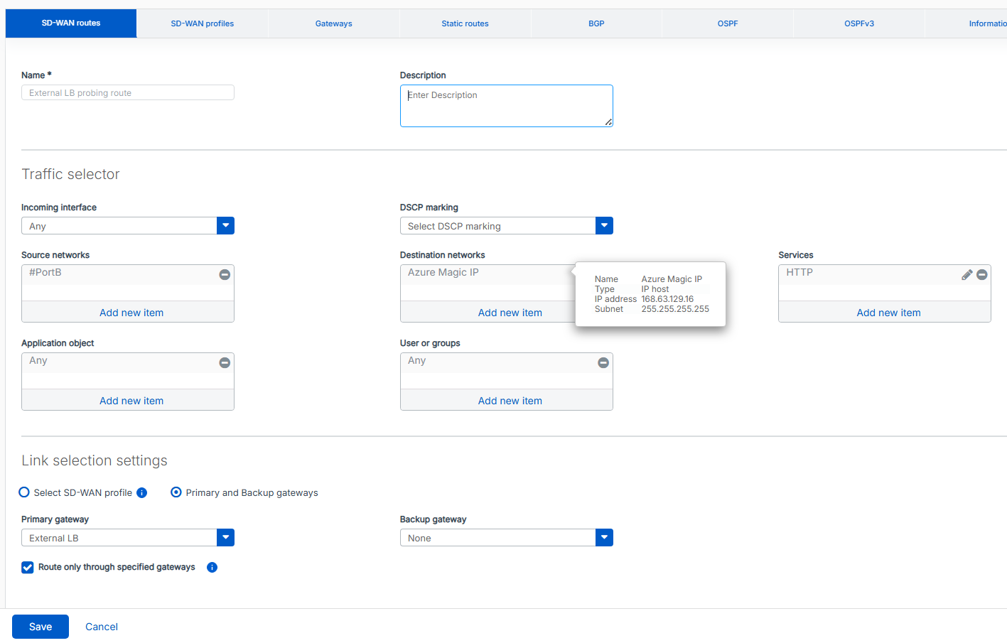
-
Click Save.
-
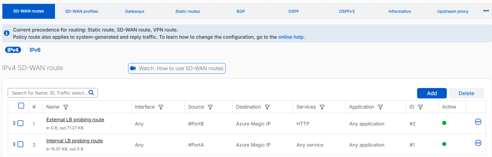
Make sure that the external load balancer route is prioritized above the internal load balancer route. This configuration allows the internal load balancer on #PortA to pass its health check probe successfully.
Repeat these steps for the second firewall.
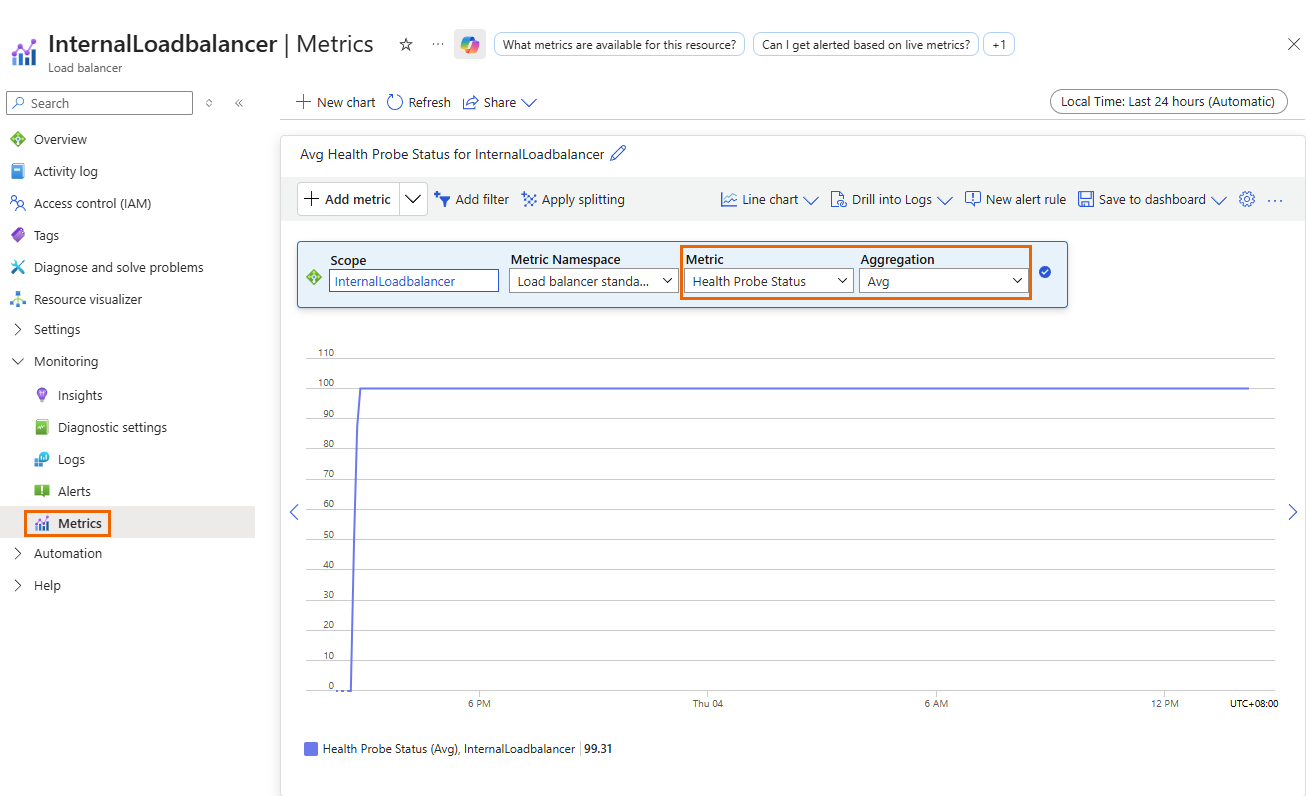
Verify the health probes
The health probe status metric indicates the health of the firewall instances based on the load balancer's configuration. Azure uses this status to determine where to route new connections. Health probes originate from an Azure infrastructure IP address and are visible within the VM's operating system.
To verify the health probe status, do as follows:
- Sign in to the Microsoft Azure portal.
- Go to Load balancers. You can also search for "load balancers" in the search bar.
- Select the load balancer you want to check.
- Click Monitoring > Metrics.
- Under Metric, select Health probe status.
-
Under Aggregation, select Avg.
-
Click Add filter, then do as follows:
- Under Property, select Backend IP address.
- Under Operator, select =.
- Under Values, select the IP address you want to monitor.

You can apply additional filters as needed.
Make sure that none of the firewall IP addresses show a health probe status of 0. If a status of 0 occurs, the firewall is removed from the pool of healthy instances.
Route internet traffic through the firewalls
To route internet traffic from devices behind the internal load balancer through the firewalls, configure an Azure route table and create a firewall rule. This setup ensures that internet traffic from the LAN flows through the internal load balancer and is then distributed across both firewalls using a load-balancing method.
Microsoft Azure
In the Azure portal, do as follows:
- Sign in to the Microsoft Azure portal.
- Go to Route tables. You can also search for "route tables" in the search bar.
- Click Create.
-
Configure the following settings:
Setting Value Project details Subscription Select your subcription. Resource group Select your resource group. Instance details Name Enter a name. Propagate gateway routes Select Yes. Region Select the same region you used. 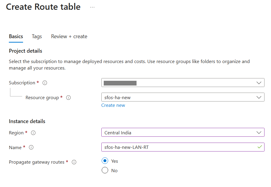
-
Click Review + create.
- Click Create.
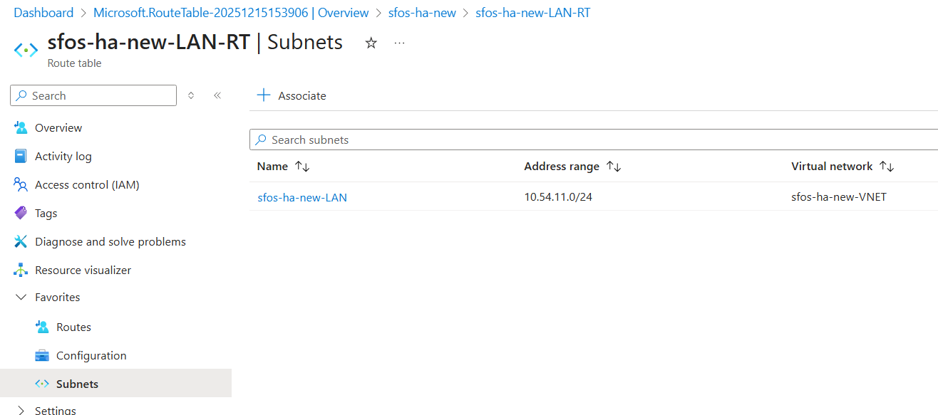
- Click Go to resource and click Subnets.
- Click Associate.
-
Configure the following settings:
Setting Value Virtual network Select your virtual network. Subnet Select the network of the internal load balancer.
In this example, it's
10.54.11.0/24. -
Click OK.
-
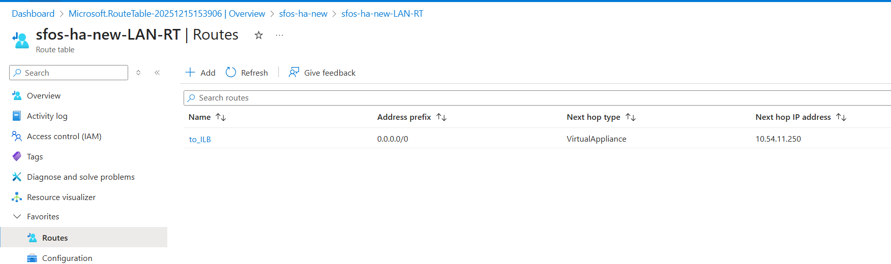
Click Routes, then click Add.
-
Configure the following settings:
Setting Value Route name Enter a name. Destination type Select IP address. Destination IP addresses/CIDR ranges Enter 0.0.0.0/0.Next hop type Select Virtual appliance. Next hop address Enter the IP address of the internal load balancer.
In this example, it's
10.54.11.250. -
Click Add.
Firewall
In the firewall, do as follows:
- Connect to the first firewall using port
4444, then sign in. See Connecting to the firewalls. - Go to Rules and policies > Firewall rules.
- Select IPv4 protocol.
- Click Add firewall rule and select New firewall rule.
-
Configure the following settings:
Setting Value Rule name Enter a name. Action Select Accept. Log firewall traffic Select this option. Source zone Select LAN. Source networks and devices Remove Any and click Add new item to create a network address host for the LAN network.
In this example, it's
10.54.11.0/24.Destination zones Select WAN. Destination networks Select Any. 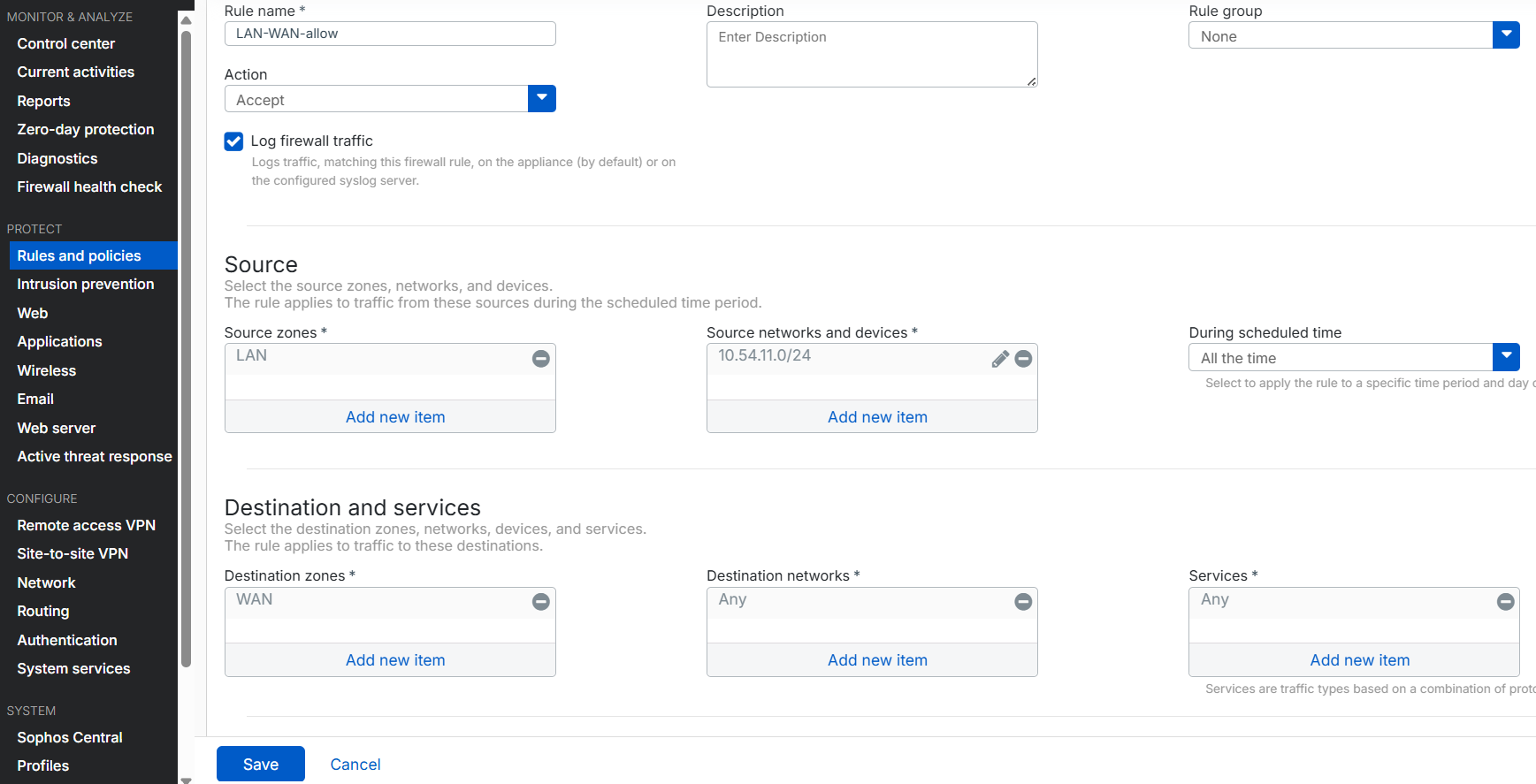
-
Click Save.
Repeat these steps for the second firewall.
Allow access to internal devices through the external load balancer
Referring to the network diagram above, consider the example of accessing the RDP device at 10.54.11.6 from the internet. Incoming traffic first reaches the external load balancer, which uses health check probes to determine availability and then forwards the traffic to one of the firewalls.
Microsoft Azure
In the Azure portal, do as follows:
- Sign in to the Microsoft Azure portal.
- Go to Load balancers. You can also search for "load balancers" in the search bar.
- Select your external load balancer.
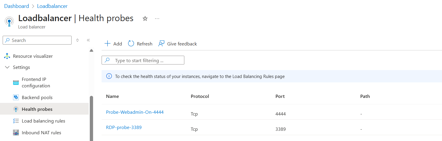
- Go to Settings > Health probes and click Add.
-
Configure the following settings:
Setting Value Name Enter a name. Protocol Select TCP. Port Enter 3389. -
Click Save.
-
Go to Settings > Load balancing rules and click Add.
-
Configure the following settings:
Setting Value Name Enter a name. IP version Select IPv4. Frontend IP address Select your external load balancer frontend IP address. Backend pool Select your external load balancer backend pool. Protocol Select TCP. Port Enter 3389.Backend port Enter 3389.Health probe Select the health probe for port 3389.Session persistence Select Source IP and protocol. 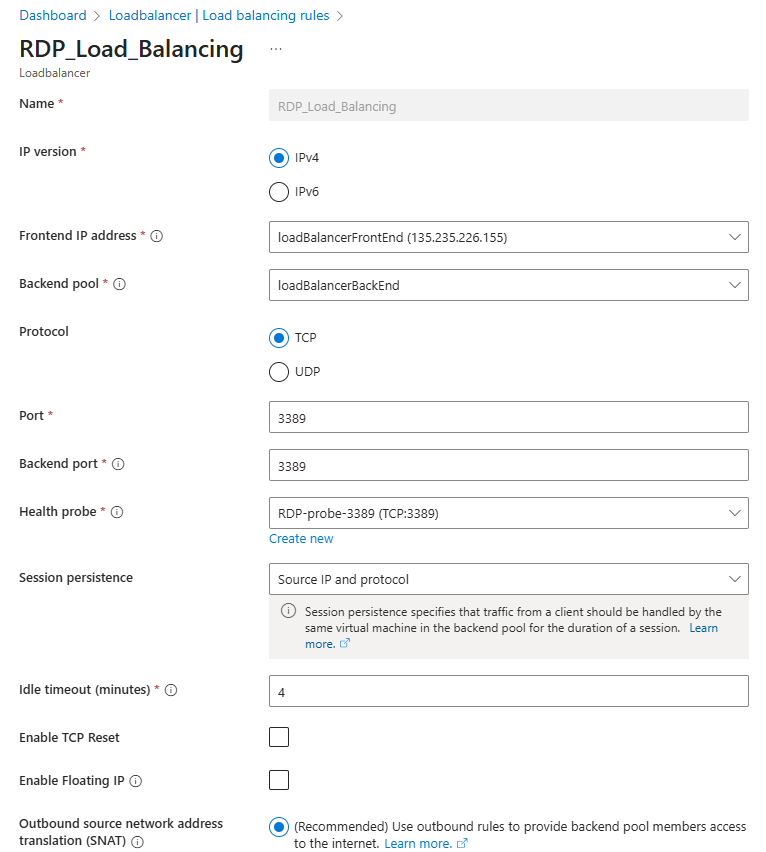
-
Click Save.
- Go to Network security groups. You can also search for "network security groups" in the search bar.
- Select the NSG associated with the firewalls.
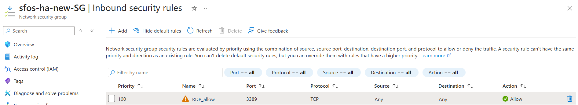
- Go to Settings > Inbound security rules and click Add.
-
Configure the following settings:
Setting Value Source Select Any.
To make the rule more secure and specific, allow only the public IP addresses of administrators or users who need RDP access.
Destination port ranges Enter 3389.Protocol Select TCP. Action Select Allow. Name Enter a name. -
Click Add.
Firewall
In the firewall, do as follows:
- Connect to the first firewall using port
4444, then sign in. See Connecting to the firewalls. - Go to Rules and policies > Firewall rules.
- Select IPv4 protocol.
- Click Add firewall rule and select New firewall rule.
-
Configure the following settings:
Setting Value Rule name Enter a name. Action Select Accept. Log firewall traffic Select this option. Source zone Select WAN. Source networks and devices Select Any. Destination zones Select LAN. Destination networks Select the WAN port.
In this example, it's #PortB.
Services Remove Any and click Add new item to create a service host for TCP port 3389.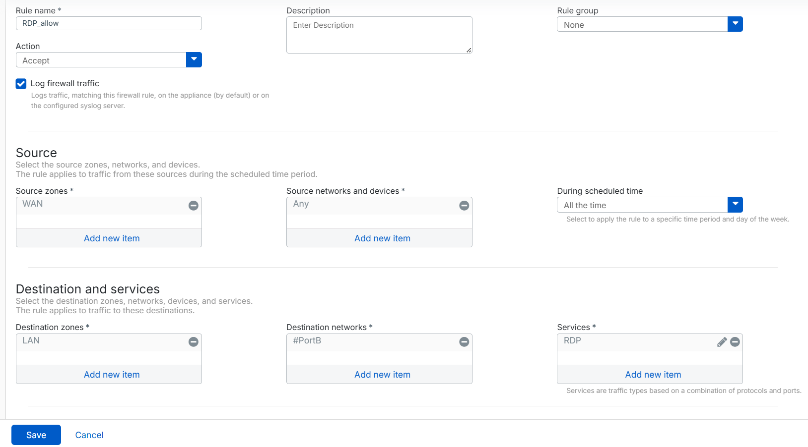
-
Click Save.
- Go to Rules and policies > NAT rules.
- Select IPv4 protocol.
- Click Add NAT rule and select New NAT rule.
-
Configure the following settings:
Setting Value Rule name Enter a name. Original source Select Any. Original destination Select the WAN port.
In this example, it's #PortB.
Original service Remove Any and select the RDP service you created. Translated source (SNAT) Select MASQ. Translated destination (DNAT) Click the drop-down list and click Add to create an IP address host for the RDP server.
In this example, it's
10.54.11.6Translated service (PAT) Select Original. 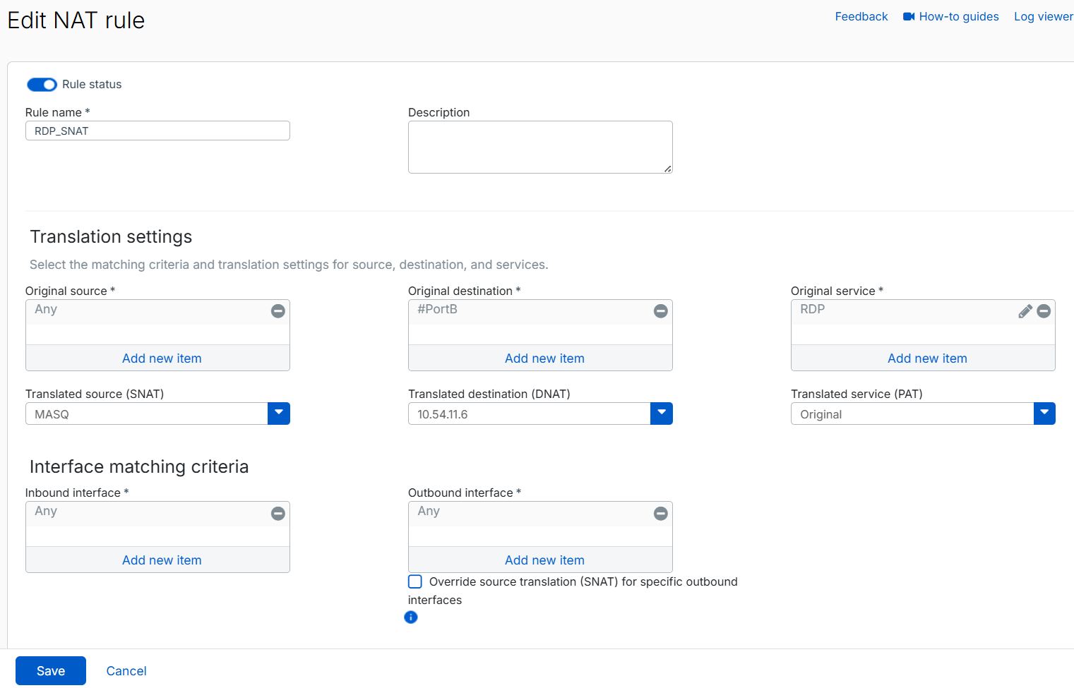
Because we configured Translated source (SNAT) as MASQ, RDP traffic is translated to the firewall's LAN IP address before reaching the RDP server. This prevents asymmetric routing issues that occur when request traffic from one firewall is routed through the internal load balancer, but the response traffic is sent through another firewall, breaking the traffic flow.
-
Click Save.
Repeat these steps for the second firewall.
Troubleshooting
This section describes common issues and their solutions related to deploying an active-active HA cluster in Azure.
Common reasons health probes fail
The most common reasons health probes fail are as follows:
-
Incorrect port or protocol
The health probe is configured for a port that isn't listening, isn't responding, or uses the wrong protocol.
If your service uses Direct server return (DSR) or floating IP rules, make sure the service listens on the NIC's IP address configuration, not the loopback address bound to the frontend IP address.
-
Blocked by security rules
The probe may be blocked by any of the following security rules:
- Network security group (NSG) rules
- The VM's guest OS firewall
- Application-layer filters
-
Missing special routes after a firmware upgrade
The routes injected by the automation runbook aren't persistent across firmware upgrades. After upgrading the firewall firmware, rerun the automation runbook to reinject the special routes for the internal load balancer.
Internal load balancer health status shows unhealthy or 100% probe loss
The routes for Azure's IP address 168.63.129.16 are injected into the kernel routing table to enable successful health probes for the internal load balancer. These routes aren't persistent across firmware upgrades.
After upgrading the firewall VM firmware, these routes are removed from the routing table. As a result, the internal load balancer health status becomes unhealthy or shows 100% probe loss for both firewalls, which can cause users to lose internet access.
To restore healthy status for the internal load balancer probes, do as follows:
- In the Azure portal, go to Home > Network security groups.
- Select the NSG associated with the firewalls.
-
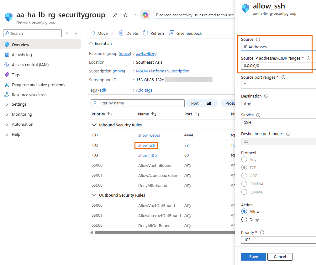
Under Inbound security rules, click allow_ssh, then do as follows:
- Under Source, select IP address.
- Under Source IP addresses/CIDR ranges, enter
0.0.0.0/0. - Click Save.
-
Next to Resource group, click your resource group.
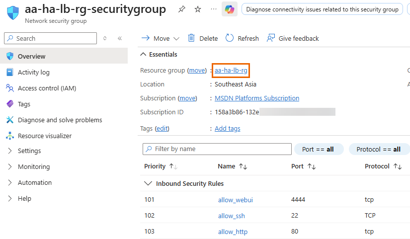
-
Search for the runbook and select it.
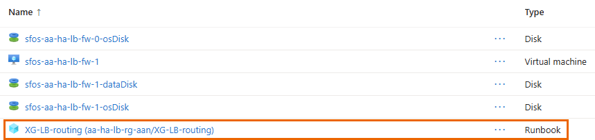
-
Click Edit > Edit in portal.
-
Comment out lines 20 to 24 by adding
#at the beginning of each line.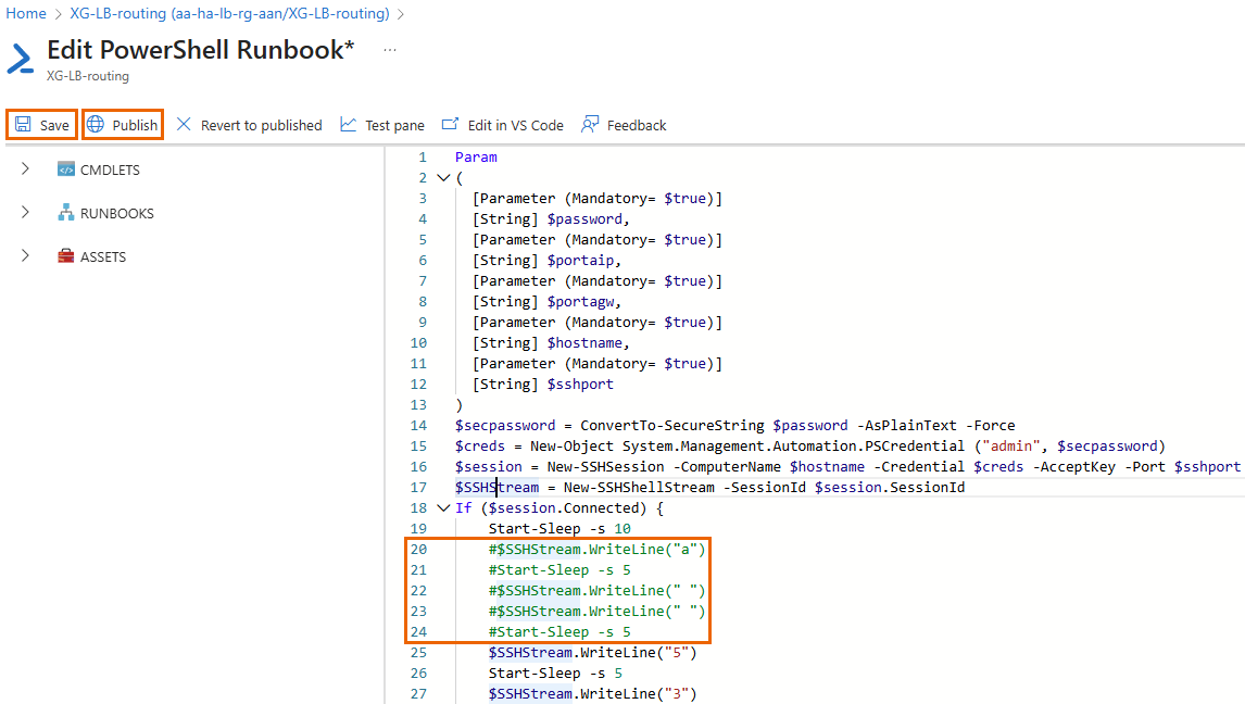
-
Click Save, then Publish, and confirm by clicking Yes.
The updated script will run during the next execution cycle.
-
Click Start.
-
Using the details of the first firewall VM, configure the following settings:
Setting Value Password Enter the Admin password you created. portaip Enter the private IP address of PortA (LAN). For example, 10.0.2.5.portagw Enter the gateway IP address of the LAN.
This is usually the first IP address of the LAN subnet in Azure. In this example, it's
10.0.2.1.Hostname Enter the DNS name or the public IP address. sshport Enter the public SSH port for CLI access. For example, port 2222.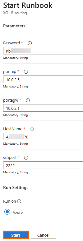
Tip
To view interface details, go to Home > Network interfaces in the Azure portal.
-
Click Start.
If successful, the status changes to Completed, and the firewall VM restarts. This process reinjects the routes for the Azure IP address
168.63.129.16, restoring internal load balancer health probes.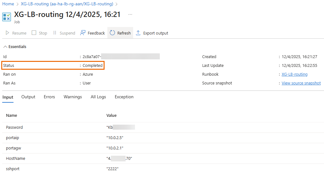
-
Repeat these steps for the second firewall VM after upgrading its firmware.
After completing this process, the internal load balancer health probe for both firewalls will return to 100% health, and internet connectivity will be restored.
-
(Optional) To verify the internal load balancer's status, do as follows:
- In the Azure portal, go to Home > Resource manager > Resource groups, then select your resource group.
- Click Internalloadbalancer.
-
Click Monitoring > Insights.
You should see a green checkmark
 for both firewalls.
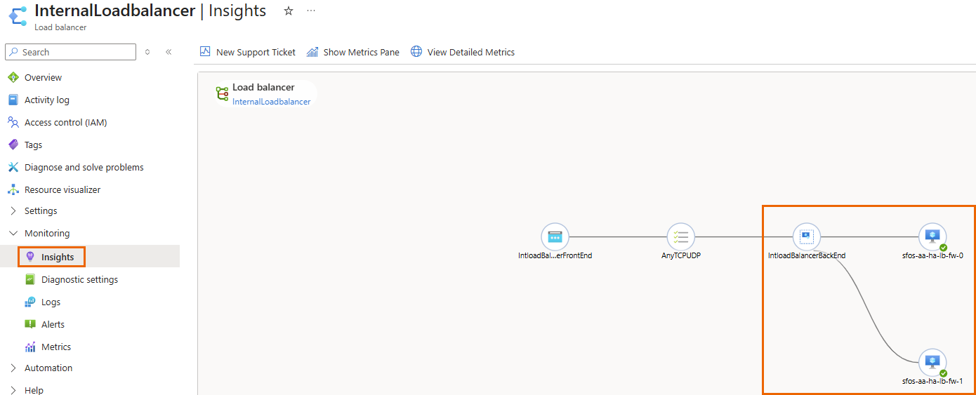
-
After completing the process, revert SSH access to the allowed IP addresses. Do as follows:
- In the Azure portal, go to Home > Network security groups.
- Select the NSG associated with the firewalls.
-
Under Inbound security rules, click allow_ssh, then do as follows:
- Under Source, select IP address.
- Under Source IP addresses/CIDR ranges, enter your organization's allowed IP addresses.
- Click Save.