On the RED Management > Client Management page you can enable remote Sophos UTM units to connect to your Sophos UTM using a Remote Ethernet Device (RED) tunnel. The remote Sophos UTM units then simply act like RED appliances. Furthermore you can configure RED appliances manually (expert mode) instead of using the deployment helper. The deployment helper is a more convenient way to configure RED appliances and can be found on the next WebAdmin page.
Each RED appliance or Sophos UTM that is configured here is able to establish a connection to your Sophos UTM.
The [Server] tag in front of the page name indicates that this page only needs configuration if Sophos UTM should act as server (RED hub).
Note – For RED appliances to be able to connect, you need to enable RED support on the Global Settings page first.
Setting up a RED tunnel between two Sophos UTM units
To enable another Sophos UTM to connect to your local Sophos UTM using a RED tunnel, do the following:
-
On the Client Management tab, click Add RED.
The Add RED dialog box opens.
-
Make the following settings:
Branch name: Enter a name for the branch where the client Sophos UTM is located, e.g. "Office Munich".
Client type: Use RED Firewall Server to establish a connection using the RED protocol version 2. Select RED Firewall Legacy only if the remote UTM doesn’t have version 9.7 or newer.
Tunnel ID: By default, Automatic is selected. Tunnels will be numbered consecutively. You need to make sure that the tunnel ID is unique for both Sophos UTM units. In this case you might need to select another ID from the drop-down list.
Comment (optional): Add a description or other information.
-
Click Save.
Sophos UTM object is being created.
-
Download the provisioning file.
To provide the remote (client) Sophos UTM with the configuration data download the provisioning file using the Download button and transfer the file to the remote Sophos UTM in a secure way.
Configuring a RED appliance
To enable a RED appliance to connect to your local Sophos UTM, do the following:
-
On the Client Management tab, click Add RED.
The Add RED dialog box opens.
-
Make the following settings:
Branch name: Enter a name for the branch where the RED appliance is located, e.g. "Office Munich".
Client type: Select a RED client type from the drop-down list, depending on the type of RED appliance you want to connect.
Note – The RED 50 appliance has an LCD display. It can be used to show you important information about the device. With the Left button you can enter the menu. Navigate with the Up and Down button and enter with the Right button. Please see the Operating Instructions for further information.
RED ID: Enter the ID of the RED appliance you are configuring. This ID can be found on the back of the RED appliance and on its packaging.
Tunnel ID: By default, Automatic is selected. Tunnels will be numbered consecutively. In case you have conflicting IDs, select another ID from the drop-down list.
Unlock code (optional): For the first deployment of a RED appliance, leave this box empty. In case the RED appliance you are configuring has been deployed before, you need to provide its unlock code. The unlock code is generated during the deployment of a RED appliance, and is emailed instantly to the address provided on the Global Settings tab. This is a security feature, which ensures that a RED appliance cannot simply be removed and installed elsewhere.
Note – For manual deployment via USB stick and automatic deployment via RED Provisioning Service (see below), two separate unlock codes are generated. If you switch a RED device from one deployment method to the other, make sure to use the corresponding unlock code: For manual deployment, provide the unlock code of the last manual deployment; for automatic deployment, provide the unlock code of the last automatic deployment.
If you are not in the possession of the unlock code, the only way to unlock the RED appliance is to contact the Sophos Support. The Support however can only help you if you deployed the configuration automatically, via the Sophos RED Provisioning Service.
Tip – The unlock code can also be found in the backup file of Sophos UTM the RED was connected to in case that the backup contains host-specific data.
UTM hostname: You need to enter a public IP address or hostname where Sophos UTM is accessible.
2nd UTM hostname (with RED 15(w), 20, 50, and 60): You can enter another public IP address or hostname of the same Sophos UTM. Note that you cannot enter the IP or hostname of a different Sophos UTM.
Use 2nd hostname for: You can configure what the second hostname should be used for.
- Failover: Select to only use the second hostname in case the first hostname fails.
- Balancing: Select to activate active load balancing between both hostnames. This makes sense if both uplinks the first and the second hostname correlate to, are equal in latency and throughput.
Uplink mode/2nd uplink mode: You can define how the RED appliance receives an IP address, which can be either via DHCP or by directly assigning a static IP address. For RED 50 and 60 you define the uplink mode for each RED uplink Ethernet port separately.
- DHCP client: The RED pulls an IP address from a DHCP server.
- Static address: Enter an IPv4 address, a corresponding netmask, a default gateway and a DNS server.
Note – There is no one-to-one association between Sophos UTM hostname and RED uplink Ethernet port. Each RED port will try to connect to each defined Sophos UTM hostname.
Use 2nd uplink for (with RED 50 and 60, see images below): You can configure what the second uplink should be used for.
- Failover: Select to only use the second uplink in case the first uplink fails.
- Balancing: Select to activate active load balancing between both uplinks. This makes sense if both uplinks on the RED are equal in latency and throughput.
Operation mode: You can define how the remote network will be integrated into your local network.
Note – If you use RED 15w as access point it is recommended that you read the chapter RED Management > RED 15w especially if you are facing any configuration issues.
- Standard/Unified: Sophos UTM completely controls the network traffic of the remote network. Additionally, it serves as DHCP server and as default gateway. All remote network traffic will be routed through Sophos UTM.
- Standard/Split: Sophos UTM completely controls the network traffic of the remote network. Additionally, it serves as DHCP server and as default gateway. In contrast to the Unified mode, only certain traffic will be routed through Sophos UTM. Define local networks in the Split Networks box below which can be accessed by remote clients.
- Transparent/Split: Sophos UTM does not control the network traffic of the remote network, it does neither serve as DHCP server nor as default gateway. On the contrary, it pulls an IP address from the DHCP server of the remote network to become a part of that network. However, you can enable access for remote clients to your local network. For that you need to define Split Networks that are allowed to be accessed by the remote network. Additionally, you can define one or more Split Domains to be accessible. If your local domains are not publicly resolvable, you need to define a Split DNS Server, which can be queried by remote clients.
Note – VLAN tagged frames cannot be handled with this operation mode.
Note – VLAN tagged frames cannot be handled with this operation mode.
You can find examples for all the operation modes on the Deployment Helper tab.
-
For RED 50 or 60, optionally make the following switch port configuration settings:
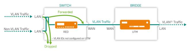
LAN port mode: RED 50 and 60 offer four LAN ports that can be configured either as simple switches or for intelligent VLAN usage. When set to Switch, all traffic will basically be sent to all ports. When set to VLAN, traffic can be filtered according to the Ethernet frames' VLAN tag, thus allowing to tunnel more than one network into the RED tunnel.
LAN modes: When using the VLAN switch port configuration, you can configure each LAN port separately. For each LAN port, the following options are available:
Untagged: Ethernet frames with the VLAN IDs specified in the LAN VID(s) field below will be sent to this port. The frames are sent without tags, thus the end devices do not have to support VLAN. This port allows just one VLAN ID.

LAN mode: Untagged
Untagged, drop tagged: Ethernet frames with the VLAN IDs specified in the LAN VID(s) field below will not be sent to this port. The frames are sent without tags, thus the end devices do not have to support VLAN.

LAN mode: Untagged, drop tagged
Tagged: Ethernet frames with the VLAN IDs specified in the LAN VID(s) field below will be sent to this port. The frames are sent with tags, and the end devices have to support VLAN. Frames without VLAN IDs will not be sent to this port. This port allows up to 64 different VLAN ID(s) separated by comma.
LAN mode: Tagged
Disabled: This Port is closed. No frames with or without VLAN IDs specified in the LAN VID(s) will be sent to this port.

LAN mode: Disabled
Note – The LAN modes have different names in the Cisco/HP documentation. Untagged also known as 'Hybrid Port', Untagged, drop tagged also known as 'Access Port' and Tagged also known as 'Trunk Port'.
Comment (optional): Add a description or other information.
Cross Reference – For more information about VLAN tagging for RED 50 or 60, see the Sophos Knowledge Base and more information about tunnel compression, see also the Sophos Knowledge Base.
-
For RED 60, you can turn on Power over Ethernet for one or both ports.
-
Optionally, make the following advanced settings:
MAC filtering type: To restrict the MAC addresses allowed to connect to this RED appliance, select Blacklist or Whitelist. With Blacklist, all MAC addresses are allowed except those listed on the MAC address list selected below. With Whitelist, all MAC addresses are prohibited except those listed on the MAC address list selected below.
MAC addresses: The list of MAC addresses used to restrict access to the RED appliance. MAC address lists can be created on the Definitions & Users > Network Definitions > MAC Address Definitions tab. To restrict access to a RED appliance, you can add a maximum of 200 MAC addresses for RED 10, 300 for RED 15(w), and 400 for RED 20, 50, and 60.
Note – MAC filtering only works for RED rev. 2 or newer.
Device deployment: Select how you want to provide the necessary configuration settings for the RED appliance. By default, Sophos UTM provides the RED's configuration data automatically via the RED Provisioning Service of Sophos. In this case, the RED appliance receives its configuration via Internet. The RED appliance connects to a Sophos NTP server and receives the system time. If for example your RED does not have an Internet connection, you can provide the configuration manually, via USB stick. If you deploy a RED device manually, you have to ensure that Sophos UTM is acting as NTP server. Therefore activate NTP on Sophos UTM and allow the correct network or at least the IP address of the RED.
Note – Sophos UTM version 9.2 or earlier: After you deployed a RED manually you need to deploy it once using the RED Provisioning Service (automatically) before you can deploy it manually again. Manual device deployment only works for RED appliances with firmware version 9.1 or later.
Caution – If you select manual deployment, it is extremely important to keep the unlock code, which is sent by email. If you lose the unlock code, you can never again connect the RED appliance to another Sophos UTM.
Tunnel compression: Enabling tunnel compression will compress all traffic that is sent through the RED tunnel. Tunnel compression might increase the throughput of the RED appliance in areas with a very slow Internet connection such as 1-2 Mbps. However, any performance increase mainly depends on the entropy of the data being sent (for example, already compressed data such as HTTPS or SSH cannot be compressed any further). In some circumstances it might therefore be possible that enabling tunnel compression could actually reduce the throughput of the RED appliance. In that case, please disable tunnel compression.
Note – Tunnel compression is not available for RED 10 rev.1.
3G/UMTS failover: Starting with RED rev. 2, the RED appliance offers a USB port, where you can plug in a 3G/UMTS USB stick. If selected, this stick can serve as Internet uplink failover in case of a WAN interface failure. For the necessary settings please refer to your Internet provider's data sheet.
- Username/Password (optional): If required, enter a username and password for the mobile network.
-
PIN (optional): Enter the PIN of the SIM card if a PIN is configured.
Note – If you enter a wrong PIN, in case of a WAN interface failure, the connection via 3G/UMTS cannot be established. Instead, the 3G/UMTS failover checkbox of the RED appliance will automatically be unselected. Thus, the wrong PIN will only be used once. When the WAN interface comes up again, a warning will be displayed for the RED appliance: A wrong PIN was entered for 3G/UMTS failover uplink. Please change the login data. When you open the Edit RED dialog box, a message is displayed which tells you that the 3G/UMTS failover was automatically unselected. Correct the PIN before selecting the checkbox again. Please note that after three connection attempts with a wrong PIN, the SIM card will be locked. Unlocking cannot be done via the RED appliance or Sophos UTM. The signal strength for most supported 3G/UMTS USB sticks is displayed in the live log and the RED 50 LCD display.
- APN: Enter your provider's Access Point Name information.
- Dial string (optional): If your provider uses a different dial string, enter it here. Default is *99#.
Note – You always have to make the following configurations manually: 1) Creating the necessary firewall rules (Network Protection > Firewall > Rules). 2) Creating the necessary masquerading rules (Network Protection > NAT > Masquerading).
-
Click Save.
The RED appliance is being created and appears on the RED list.
With automatic device deployment, as soon as the RED has booted, it will fetch its configuration at the Sophos RED Provisioning Service (RPS ). After that the connection between your Sophos UTM and the RED appliance is going to be established.
With manual device deployment, the new entry in the RED list will have a Download button. Download the configuration file and save it to the root directory of a USB stick. Then plug the USB stick into the RED appliance before turning it on. The RED will fetch its configuration from the USB stick. After that the connection between your Sophos UTM and the RED appliance is going to be established.
Caution – It is crucial that you keep the unlock code, which is emailed instantly to the address provided on the Global Settings tab as soon as the RED appliance receives its configuration. (In case of switching between manual and automatic deployment, make sure to keep both unlock codes.) You need the unlock code when you want to use the RED appliance with another Sophos UTM. If you then do not have the unlock code ready, the only way to unlock the RED appliance is to contact the Sophos Support. The Support however can only help you if you deployed the configuration automatically, via the Sophos RED Provisioning Service.
To edit a RED appliance, click the corresponding button. You can see the appliance status of all configured RED appliances on the RED overview page of WebAdmin.
The following images give an overview of the four balancing and failover combinations RED 50 and 60 provide. Solid lines reflect balancing, dotted lines failover behavior:

RED 50: Hostname and Uplink Balancing (turquoise) and Hostname and Uplink Failover (red)

RED 50: Hostname Balancing and Uplink Failover (green) and Hostname Failover and Uplink Balancing (blue)
Deleting a RED appliance
To delete a RED appliance, click the Delete button next to the appliance name.
There will be a warning that the RED object has dependencies. Be aware that deleting a RED appliance will not delete associated interfaces and their dependencies. This is intentional, since it enables you to move an interface from one RED appliance to another.
If you want to remove a RED appliance setup completely, you need to delete potential interface and other definitions manually.
 Related Topics