Configure access layer switches for XGS HA
The following network diagram shows the network configuration used as a reference in this guide.
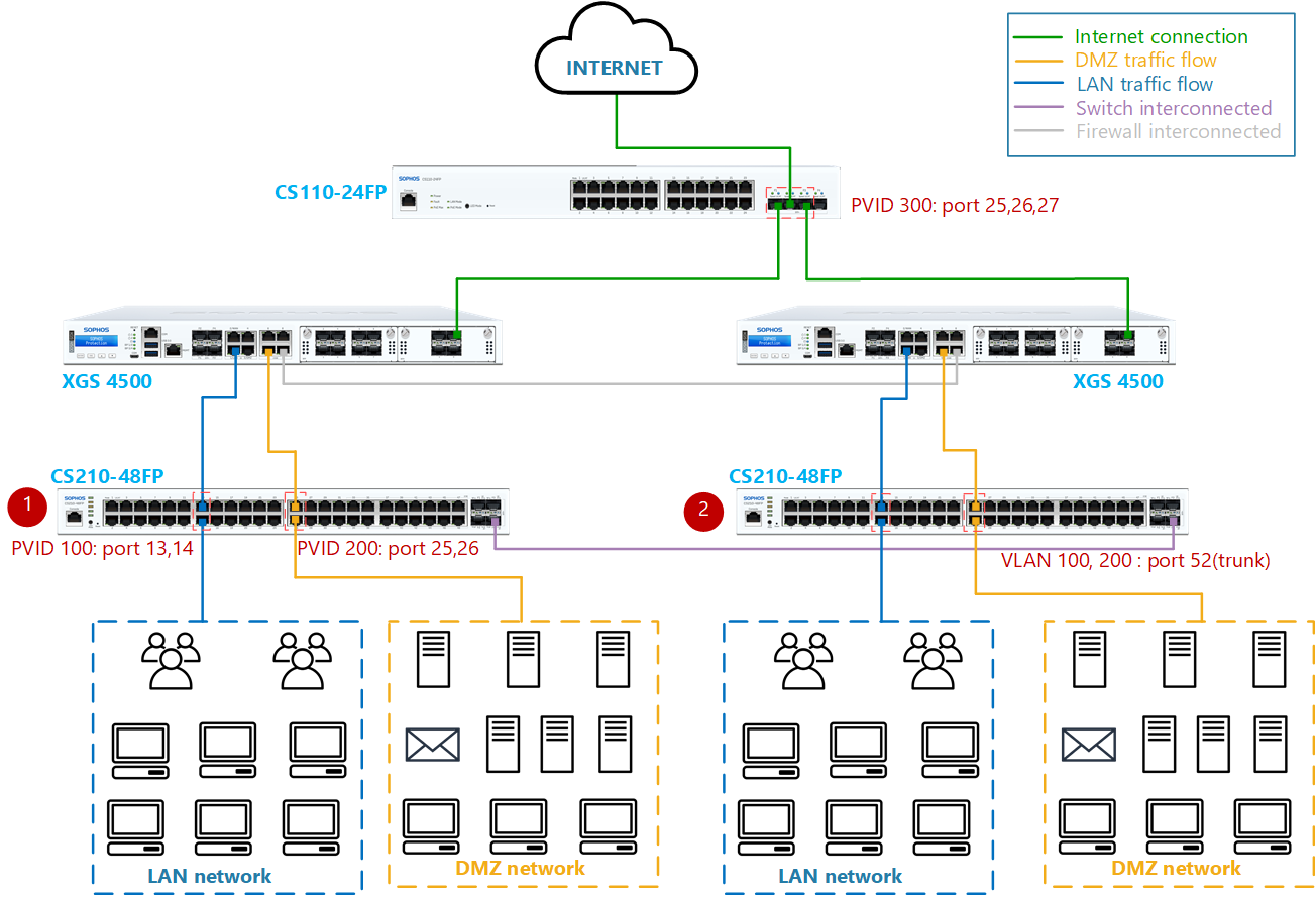
Connectivity details:
- Port1 of the firewall is connected to Port14 of the CS210-48FP switch.
- Port13 of the CS210-48FP switch is connected to the LAN network.
- Port5 of the firewall is connected to Port26 of the CS210-48FP switch.
- Port25 of the CS210-48FP switch is connected to the DMZ network.
- Port t4 of the firewall is connected to Port25 and Port27 of the CS110-24FP switch.
- Port26 of CS110-24FP switch connected to the internet.
- Port7 of both the firewall devices is a dedicated HA link port connected to each other directly.
- Port52 of both CS210-48FP switches is connected directly as a redundant port.
To configure your switches, do as follows:
Configure the CS110-24FP switch
-
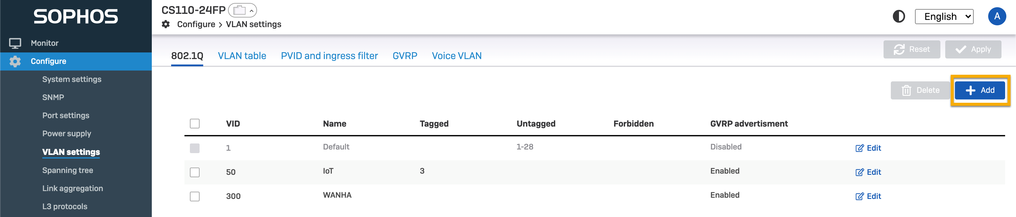
Go to Configure > VLAN settings > 802.1Q.
- Click Add and create VLAN ID
300. - Enter a name for the VLAN.
- Click Add and create VLAN ID
-
Click Apply to save the changes.
Here's an example:
-
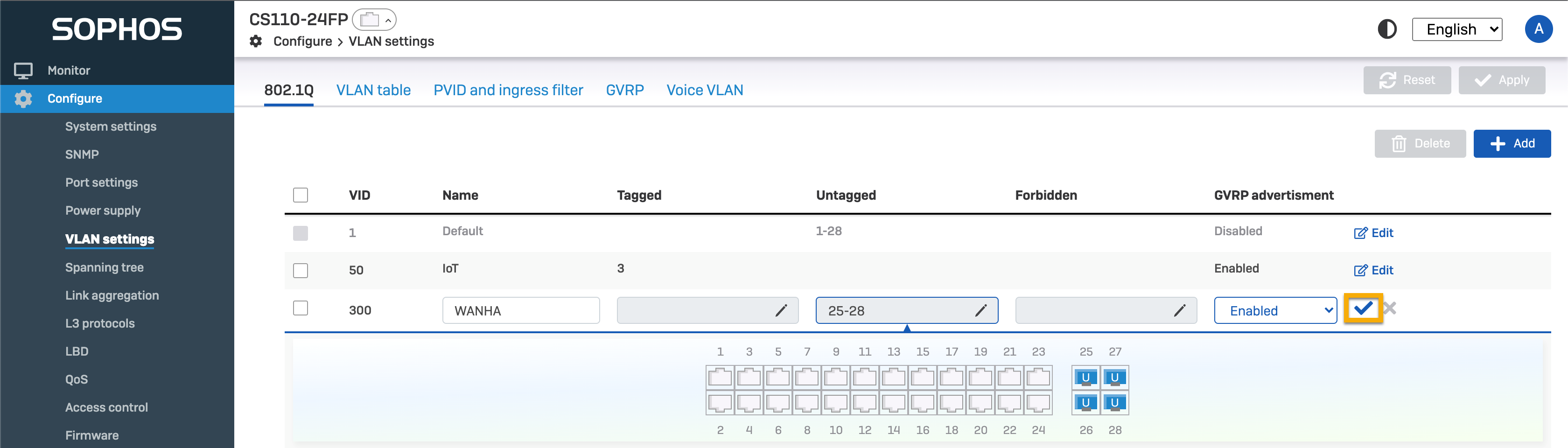
Click Edit, select the Untagged text box, select ports 25, 26, and 27, and click the tick mark.
-
Click Apply to save the changes.
-
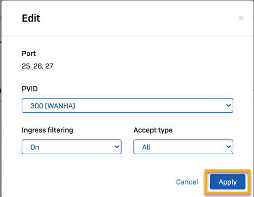
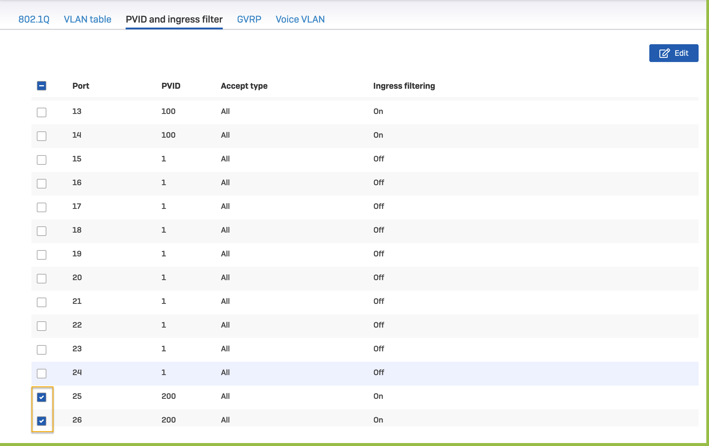
Go to PVID and ingress filter.
- Select ports 25, 26, and 27, and then click Edit.
-
Select the following settings:
- PVID: 300 (WANHA).
- Ingress filtering: On.
- Accept type: All.
-
Click Apply.
-
Sign in to the switch CLI and enter the configuration mode.
configure terminal -
Create VLAN
300.vlan 300 -
Name the VLAN WANHA.
ports name WANHA -
Assign the tagged and untagged ports for the VLAN.
ports add gigabitethernet 0/25-27 untagged gigabitethernet 0/25-27 -
Exit the VLAN configuration.
exit -
Select ports 25, 26, and 27.
interface range gigabitethernet 0/25-27 -
Assign PVID
300to ports 25, 26, and 27.switchport pvid 300 -
Set acceptable frame types for the ports.
switchport acceptable-frame-type all -
Turn on the ingress filter.
switchport ingress-filter -
Exit the interface configuration mode.
exit -
Exit the configuration mode.
exit -
Save the configuration.
save
Configure both the CS210-48FP switches using the local web UI
-
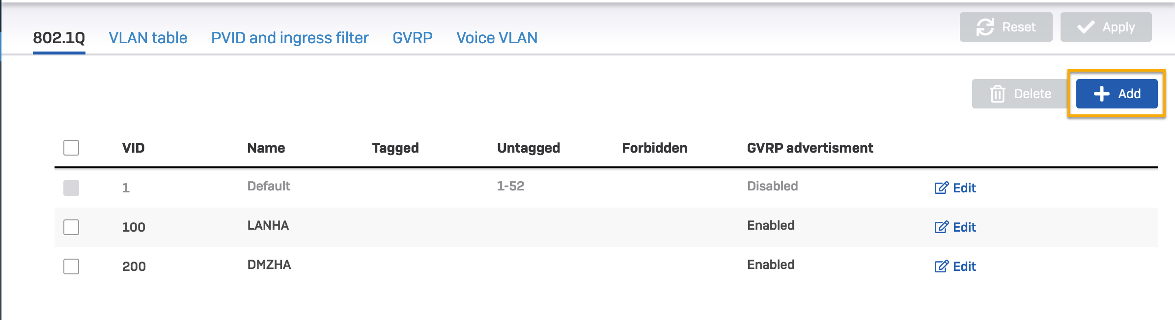
Go to Configure > VLAN settings > 802.1Q.
- Click Add, and create the VLAN IDs
100and200. - Enter a name for the VLANs.
- Click Add, and create the VLAN IDs
-
Click Apply.
Here's an example:
-
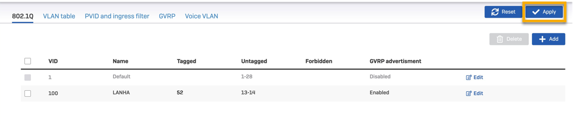
Click Edit for VLAN ID 100, select the Tagged text box and select Port 52. Select the Untagged text box, select ports 13 and 14, and click the tick mark.
-
Click Apply to save the changes.
-
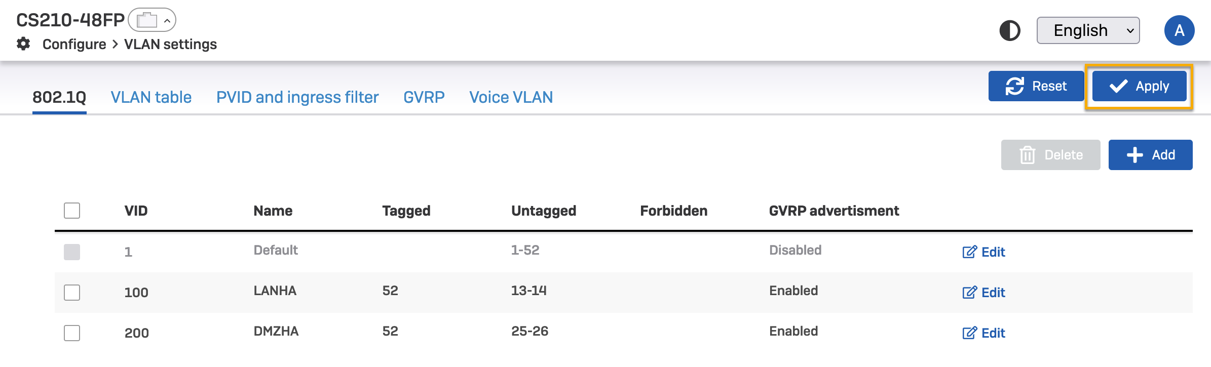
Click Edit for VLAN ID
200, select the Tagged text box and select Port 52. Select the Untagged text box, select ports 25 and 26, and click the tick mark. -
Click Apply to save the changes.
-
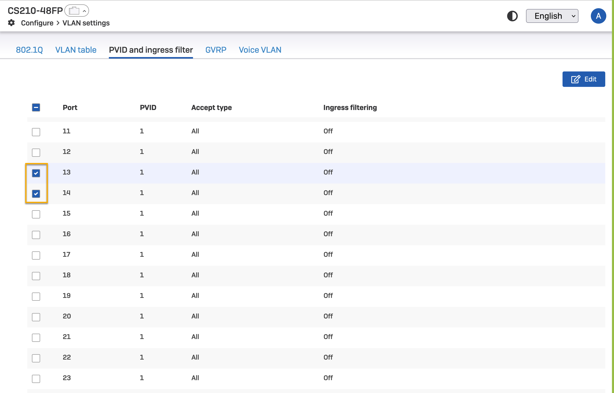
Go to PVID and ingress filter and select ports 13 and 14. Click Edit.
-
Select the following settings:
- PVID: LANHA (VLAN 100).
- Ingress filtering: On.
- Accept type: All.
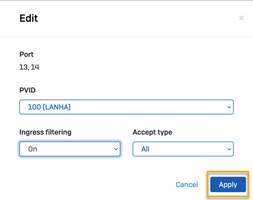
-
Click Apply.
-
Select the ports 25 and 26 and click Edit.
-
Select the following settings:
- PVID: DMZHA (VLAN 200).
- Ingress filtering: On.
- Accept type: All.

-
Click Apply.
-
Sign in to the switch CLI and enter the configuration mode.
configure terminal -
Create VLAN
100.vlan 100 -
Name the VLAN LANHA.
ports name LANHA -
Assign the tagged and untagged ports for the VLAN.
ports add gigabitethernet 0/13-14 untagged gigabitethernet 0/13-14 -
Assign port 52 to the VLAN.
ports add gigabit 0/52 -
Exit the VLAN configuration mode.
exit -
Select interfaces 13 and 14.
interface range gigabitethernet 0/13-14 -
Assign VLAN
100to ports 13 and 14.switchport pvid 100 -
Set the acceptable frame type for the port.
switchport acceptable-frame-type all -
Turn on the ingress filter for the ports.
switchport ingress-filter -
Exit the interface configuration mode.
exit -
Exit the configuration mode.
exit -
Save the configuration.
save -
Enter the configuration mode.
configure terminal -
Create VLAN
200.vlan 200 -
Name the VLAN DMZHA.
ports name DMZHA -
Add the untagged and tagged ports to the VLAN.
ports add gigabitethernet 0/25-26 untagged gigabitethernet 0/25-26 -
Add port 52 to the VLAN.
ports add gigabit 0/52 -
Exit the VLAN configuration mode.
exit -
Select ports 25 and 26.
interface range gigabitethernet 0/25-26 -
Assign VLAN
200to the ports.switchport pvid 200 -
Set the acceptable frame type for the ports.
switchport acceptable-frame-type all -
Turn on the ingress filter for the ports.
switchport ingress-filter -
Exit the interface configuration mode.
exit -
Exit the configuration mode.
exit -
Save the configuration.
save
HA configuration on auxiliary Sophos Firewall (2)
-
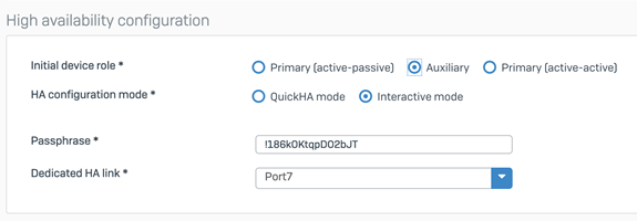
Go to System Services > High Availability and specify the settings as follows:
- Initial device role: Auxiliary.
- HA configuration mode: Interactive mode.
- Passphrase: Create your own passphrase.
- Dedicated HA Link Port: Port7. This must be the same port on both the firewall devices.
-
Click Initiate HA.
If these details aren't configured on the auxiliary device, the primary device won't be able to connect to the auxiliary device.
HA configuration on primary Sophos Firewall (1)
-
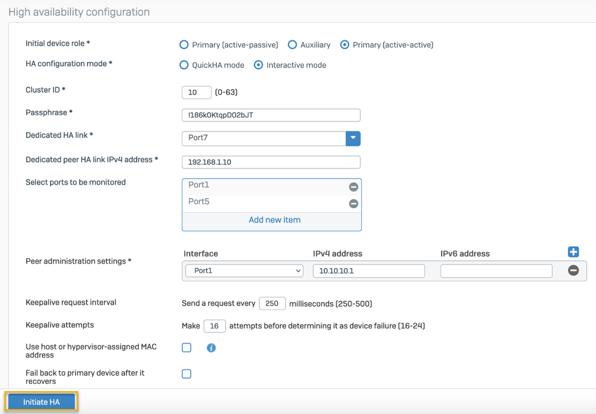
Go to System Services > High Availability and specify the settings as follows:
- Initial device role: Primary (active-active) or Primary (active-passive).
- HA configuration mode: Interactive mode.
- Cluster ID: 10 (this could be any number from 0 to 63).
- Passphrase: Enter the same passphrase as the auxiliary device.
- Dedicated HA Link: Port7 (this must be the same port as the auxiliary device).
- Dedicated peer HA Link IPv4 address: Enter the same IP address as the network.
- Select ports to be monitored: Port1, Port5 (this port is considered for HA monitoring).
- Peer administration settings: Port1. Enter the IP address of that subnet range. The web admin console of the auxiliary device can be accessed at this address.
- Keepalive request interval: 250 ms.
- Keepalive attempts: 16. The maximum number of attempts initiated by the firewall device before declaring the peer auxiliary device as unreachable.
- Fail back to primary device after it recovers: In the event of a failover, traffic is routed through the auxiliary. Select this option if you want to move back to the primary device automatically when it recovers.
-
Click Initiate HA.
Verify HA status
To check the status of HA, go to Control Center and locate the HA details widget. It shows the configured HA mode.
